- Page 1 and 2:
Operating Manual OPTIMOD 8685 Surro
- Page 3 and 4:
IMPORTANT SAFETY INSTRUCTIONS All t
- Page 5 and 6:
Manual PLEASE READ BEFORE PROCEEDIN
- Page 7 and 8:
Operating Manual OPTIMOD 8685 Surro
- Page 9 and 10:
LIMITED WARRANTY...................
- Page 11 and 12:
Advanced Two-Band Controls ........
- Page 13 and 14:
CIRCUIT DESCRIPTION................
- Page 15 and 16:
Function Description Drawing Page H
- Page 17 and 18:
C CALM Act 1- · 3 CBS Loudness Lev
- Page 19 and 20:
dual-mono mode 2- · 34 dull sound
- Page 21 and 22:
Reassembling 4- · 7 LCD display 6-
- Page 23 and 24:
DSP board 6- · 22 Encoder board 6-
- Page 25 and 26:
Resetting 8585 2- · 44 resolution
- Page 27 and 28:
Changing via terminal program 2- ·
- Page 29 and 30:
OPTIMOD SURROUND PROCESSOR INTRODUC
- Page 31 and 32:
OPTIMOD SURROUND PROCESSOR INTRODUC
- Page 33 and 34:
OPTIMOD SURROUND PROCESSOR INTRODUC
- Page 35 and 36:
OPTIMOD SURROUND PROCESSOR INTRODUC
- Page 37 and 38:
OPTIMOD SURROUND PROCESSOR INTRODUC
- Page 39 and 40:
OPTIMOD SURROUND PROCESSOR INTRODUC
- Page 41 and 42:
OPTIMOD SURROUND PROCESSOR INTRODUC
- Page 43 and 44:
OPTIMOD SURROUND PROCESSOR INTRODUC
- Page 45 and 46:
OPTIMOD SURROUND PROCESSOR INTRODUC
- Page 47 and 48:
OPTIMOD SURROUND PROCESSOR INTRODUC
- Page 49 and 50:
OPTIMOD SURROUND PROCESSOR INTRODUC
- Page 51 and 52:
OPTIMOD SURROUND PROCESSOR INTRODUC
- Page 53:
OPTIMOD SURROUND PROCESSOR INTRODUC
- Page 56 and 57:
2-2 INSTALLATION ORBAN MODEL 8685 C
- Page 58 and 59:
2-4 INSTALLATION ORBAN MODEL 8685 P
- Page 60 and 61:
2-6 INSTALLATION ORBAN MODEL 8685 A
- Page 62 and 63:
2-8 INSTALLATION ORBAN MODEL 8685
- Page 64 and 65:
2-10 INSTALLATION ORBAN MODEL 8685
- Page 66 and 67:
2-12 INSTALLATION ORBAN MODEL 8685
- Page 68 and 69:
2-14 INSTALLATION ORBAN MODEL 8685
- Page 70 and 71:
2-16 INSTALLATION ORBAN MODEL 8685
- Page 72 and 73:
2-18 INSTALLATION ORBAN MODEL 8685
- Page 74 and 75:
2-20 INSTALLATION ORBAN MODEL 8685
- Page 76 and 77:
2-22 INSTALLATION ORBAN MODEL 8685
- Page 78 and 79:
2-24 INSTALLATION ORBAN MODEL 8685
- Page 80 and 81:
2-26 INSTALLATION ORBAN MODEL 8685
- Page 82 and 83:
2-28 INSTALLATION ORBAN MODEL 8685
- Page 84 and 85:
2-30 INSTALLATION ORBAN MODEL 8685
- Page 86 and 87:
2-32 INSTALLATION ORBAN MODEL 8685
- Page 88 and 89:
2-34 INSTALLATION ORBAN MODEL 8685
- Page 90 and 91:
2-36 INSTALLATION ORBAN MODEL 8685
- Page 92 and 93:
2-38 INSTALLATION ORBAN MODEL 8685
- Page 94 and 95:
2-40 INSTALLATION ORBAN MODEL 8685
- Page 96 and 97:
2-42 INSTALLATION ORBAN MODEL 8685
- Page 98 and 99:
2-44 INSTALLATION ORBAN MODEL 8685
- Page 100 and 101:
2-46 INSTALLATION ORBAN MODEL 8685
- Page 102 and 103:
2-48 INSTALLATION ORBAN MODEL 8685
- Page 104 and 105:
2-50 INSTALLATION ORBAN MODEL 8685
- Page 106 and 107:
2-52 INSTALLATION ORBAN MODEL 8685
- Page 108 and 109:
2-54 INSTALLATION ORBAN MODEL 8685
- Page 110 and 111:
2-56 INSTALLATION ORBAN MODEL 8685
- Page 112 and 113:
2-58 INSTALLATION ORBAN MODEL 8685
- Page 114 and 115:
2-60 INSTALLATION ORBAN MODEL 8685
- Page 116 and 117:
2-62 INSTALLATION ORBAN MODEL 8685
- Page 118 and 119:
2-64 INSTALLATION ORBAN MODEL 8685
- Page 120 and 121:
2-66 INSTALLATION ORBAN MODEL 8685
- Page 122 and 123:
2-68 INSTALLATION ORBAN MODEL 8685
- Page 124 and 125:
2-70 INSTALLATION ORBAN MODEL 8685
- Page 126 and 127:
2-72 INSTALLATION ORBAN MODEL 8685
- Page 128 and 129:
2-74 INSTALLATION ORBAN MODEL 8685
- Page 130 and 131:
2-76 INSTALLATION ORBAN MODEL 8685
- Page 132 and 133:
2-78 INSTALLATION ORBAN MODEL 8685
- Page 134 and 135:
2-80 INSTALLATION ORBAN MODEL 8685
- Page 136 and 137:
2-82 INSTALLATION ORBAN MODEL 8685
- Page 138 and 139:
2-84 INSTALLATION ORBAN MODEL 8685
- Page 140 and 141:
2-86 INSTALLATION ORBAN MODEL 8685
- Page 142 and 143:
2-88 INSTALLATION ORBAN MODEL 8685
- Page 145 and 146:
OPTIMOD SURROUND PROCESSOR OPERATIO
- Page 147 and 148:
OPTIMOD SURROUND PROCESSOR OPERATIO
- Page 149 and 150:
OPTIMOD SURROUND PROCESSOR OPERATIO
- Page 151 and 152:
OPTIMOD SURROUND PROCESSOR OPERATIO
- Page 153 and 154:
OPTIMOD SURROUND PROCESSOR OPERATIO
- Page 155 and 156:
OPTIMOD SURROUND PROCESSOR OPERATIO
- Page 157 and 158:
OPTIMOD SURROUND PROCESSOR OPERATIO
- Page 159 and 160:
OPTIMOD SURROUND PROCESSOR OPERATIO
- Page 161 and 162:
OPTIMOD SURROUND PROCESSOR OPERATIO
- Page 163 and 164:
OPTIMOD SURROUND PROCESSOR OPERATIO
- Page 165 and 166:
OPTIMOD SURROUND PROCESSOR OPERATIO
- Page 167 and 168:
OPTIMOD SURROUND PROCESSOR OPERATIO
- Page 169 and 170:
OPTIMOD SURROUND PROCESSOR OPERATIO
- Page 171 and 172:
OPTIMOD SURROUND PROCESSOR OPERATIO
- Page 173 and 174:
OPTIMOD SURROUND PROCESSOR OPERATIO
- Page 175 and 176:
OPTIMOD SURROUND PROCESSOR OPERATIO
- Page 177 and 178:
OPTIMOD SURROUND PROCESSOR OPERATIO
- Page 179 and 180: OPTIMOD SURROUND PROCESSOR OPERATIO
- Page 181 and 182: OPTIMOD SURROUND PROCESSOR OPERATIO
- Page 183 and 184: OPTIMOD SURROUND PROCESSOR OPERATIO
- Page 185 and 186: OPTIMOD SURROUND PROCESSOR OPERATIO
- Page 187 and 188: OPTIMOD SURROUND PROCESSOR OPERATIO
- Page 189 and 190: OPTIMOD SURROUND PROCESSOR OPERATIO
- Page 191 and 192: OPTIMOD SURROUND PROCESSOR OPERATIO
- Page 193 and 194: OPTIMOD SURROUND PROCESSOR OPERATIO
- Page 195 and 196: OPTIMOD SURROUND PROCESSOR OPERATIO
- Page 197 and 198: OPTIMOD SURROUND PROCESSOR OPERATIO
- Page 199 and 200: OPTIMOD SURROUND PROCESSOR OPERATIO
- Page 201 and 202: OPTIMOD SURROUND PROCESSOR OPERATIO
- Page 203 and 204: OPTIMOD SURROUND PROCESSOR OPERATIO
- Page 205 and 206: OPTIMOD SURROUND PROCESSOR OPERATIO
- Page 207 and 208: OPTIMOD SURROUND PROCESSOR OPERATIO
- Page 209 and 210: OPTIMOD SURROUND PROCESSOR OPERATIO
- Page 211 and 212: OPTIMOD SURROUND PROCESSOR OPERATIO
- Page 213 and 214: OPTIMOD SURROUND PROCESSOR OPERATIO
- Page 215 and 216: OPTIMOD SURROUND PROCESSOR OPERATIO
- Page 217 and 218: OPTIMOD SURROUND PROCESSOR OPERATIO
- Page 219 and 220: OPTIMOD SURROUND PROCESSOR OPERATIO
- Page 221 and 222: OPTIMOD SURROUND PROCESSOR OPERATIO
- Page 223 and 224: OPTIMOD SURROUND PROCESSOR OPERATIO
- Page 225 and 226: OPTIMOD SURROUND PROCESSOR OPERATIO
- Page 227 and 228: OPTIMOD SURROUND PROCESSOR OPERATIO
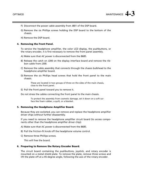
- Page 229: OPTIMOD SURROUND PROCESSOR MAINTENA
- Page 233 and 234: OPTIMOD MAINTENANCE 4-5 11. Removin
- Page 235 and 236: OPTIMOD MAINTENANCE 4-7 18. Replaci
- Page 237 and 238: OPTIMOD MAINTENANCE 4-9 most freque
- Page 239 and 240: OPTIMOD MAINTENANCE 4-11 Test Proce
- Page 241 and 242: OPTIMOD MAINTENANCE 4-13 D) LOCATE
- Page 243: OPTIMOD MAINTENANCE 4-15 SMPTE Rise
- Page 246 and 247: 5-2 TROUBLESHOOTING ORBAN MODEL 868
- Page 248 and 249: 5-4 TROUBLESHOOTING ORBAN MODEL 868
- Page 250 and 251: 5-6 TROUBLESHOOTING ORBAN MODEL 868
- Page 252 and 253: 5-8 TROUBLESHOOTING ORBAN MODEL 868
- Page 254 and 255: 5-10 TROUBLESHOOTING ORBAN MODEL 86
- Page 256 and 257: 5-12 TROUBLESHOOTING ORBAN MODEL 86
- Page 258 and 259: 6-2 TECHNICAL DATA ORBAN MODEL 8685
- Page 260 and 261: 6-4 TECHNICAL DATA ORBAN MODEL 8685
- Page 262 and 263: 6-6 TECHNICAL DATA ORBAN MODEL 8685
- Page 264 and 265: 6-8 TECHNICAL DATA ORBAN MODEL 8685
- Page 266 and 267: 6-10 TECHNICAL DATA ORBAN MODEL 868
- Page 268 and 269: 6-12 TECHNICAL DATA ORBAN MODEL 868
- Page 270 and 271: 6-14 TECHNICAL DATA ORBAN MODEL 868
- Page 272 and 273: 6-16 TECHNICAL DATA ORBAN MODEL 868
- Page 274 and 275: 6-18 TECHNICAL DATA ORBAN MODEL 868
- Page 276 and 277: 6-20 TECHNICAL DATA ORBAN MODEL 868
- Page 278 and 279: 6-22 TECHNICAL DATA ORBAN MODEL 868
- Page 280 and 281:
6-24 TECHNICAL DATA ORBAN MODEL 868
- Page 282 and 283:
6-26 TECHNICAL DATA ORBAN MODEL 868
- Page 284 and 285:
6-28 TECHNICAL DATA ORBAN MODEL 868
- Page 286 and 287:
6-30 TECHNICAL DATA ORBAN MODEL 868
- Page 288 and 289:
6-32 TECHNICAL DATA ORBAN MODEL 868
- Page 290 and 291:
6-34 TECHNICAL DATA ORBAN MODEL 868
- Page 292 and 293:
6-36 TECHNICAL DATA ORBAN MODEL 868
- Page 294 and 295:
6-38 TECHNICAL DATA ORBAN MODEL 868
- Page 296 and 297:
6-40 TECHNICAL DATA ORBAN MODEL 868
- Page 298 and 299:
J10 NOTE: D7 and D8 are not populat
- Page 300 and 301:
1 10 9 8 7 6 4 3 2 5 C +3.3 VDC Req
- Page 302 and 303:
+3.3 VDC 5 2 MECC4 3 4 MECC6 6 MECC
- Page 304 and 305:
+5 VDC 5 5 +2.5 VDC 4 4 34 42 43 48
- Page 306 and 307:
From Base Board 1 2 3 4 5 N/C 6 N/C
- Page 308 and 309:
+5V_PS1 CR1 SMAJ5.0CA +5V_PS2 CR2 S
- Page 310 and 311:
6-54 TECHNICAL DATA ORBAN MODEL 868
- Page 312 and 313:
6-56 TECHNICAL DATA ORBAN MODEL 868
- Page 314 and 315:
6-58 TECHNICAL DATA ORBAN MODEL 868
- Page 316 and 317:
+ C703 10UF C725 0.1UF POWER SUPPLY
- Page 318 and 319:
DSP CONTROL INTERFACE 62375.000.01.
- Page 320 and 321:
(SHT7) (SHT7) (SHT6) (SHT6) (SHT6)
- Page 322 and 323:
6-66 TECHNICAL DATA ORBAN MODEL 868
- Page 324 and 325:
L703 HZ0805G102R-10 C703 +3.3V 0.1U
- Page 326 and 327:
6-70 TECHNICAL DATA ORBAN MODEL 868
- Page 328 and 329:
J2 1 2 3 4 5 6 7 8 9 10 11 12 13 14
- Page 330 and 331:
From Interface Board J2 Pin 4 is au
- Page 332 and 333:
6-76 TECHNICAL DATA ORBAN MODEL 868
- Page 334 and 335:
GND 1 +5VD 4 VCC GND 2 IC201 /TOVER
- Page 336 and 337:
6-80 TECHNICAL DATA ORBAN MODEL 868
- Page 338 and 339:
6-82 TECHNICAL DATA ORBAN MODEL 868
- Page 340 and 341:
J300A BNC DUAL with CAPACITOR UPPER
- Page 342 and 343:
IN-CIRCUIT SERIAL PROGRAMMING INTER
- Page 344 and 345:
6-88 TECHNICAL DATA ORBAN MODEL 868
- Page 346 and 347:
+5VD Y902 1 2 DGND1 +3.3V_CLK 25.00
- Page 348 and 349:
+2.5V DGND +2.5V DGND +2.5V DGND +2
- Page 350 and 351:
+2.5V DGND_CLNR + C1300 47uF/10V +1
- Page 352 and 353:
6-96 TECHNICAL DATA ORBAN MODEL 868
- Page 354 and 355:
6-98 TECHNICAL DATA ORBAN MODEL 868
- Page 356 and 357:
RS485-SDI INTERFACE DGND J200 2 4 6