

Assessment of the Bill Emerson Memorial Bridge - FTP Directory ...
Assessment of the Bill Emerson Memorial Bridge - FTP Directory ...
Assessment of the Bill Emerson Memorial Bridge - FTP Directory ...
- No tags were found...

Create successful ePaper yourself
Turn your PDF publications into a flip-book with our unique Google optimized e-Paper software.
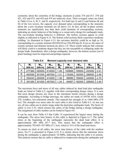
symmetric about <strong>the</strong> centerline <strong>of</strong> <strong>the</strong> bridge, moments at joints 374 and 417, 370 and421, 432 and 475, and 428 and 479 are relatively close. Their averaged values are listedin Table 6.4 as A, B, C, and D, respectively. For both top (A and C) and bottom (B andD) <strong>of</strong> <strong>the</strong> two towers, <strong>the</strong> capacity over demand ratios corresponding to <strong>the</strong> momentsabout <strong>the</strong> y-axis (in-plane moment) are all above 2.4. In fact, all <strong>the</strong> in-plane seismicmoments are significantly less than <strong>the</strong>ir yield moments <strong>of</strong> corresponding sections,indicating an elastic behavior <strong>of</strong> <strong>the</strong> bridge or a conservative design for earthquake loads.The out-<strong>of</strong>-plane bending behavior is different. The hollow sections appear to yieldslightly as indicated in Figure 6.15. The bottom solid sections likely experience moderateyielding. As illustrated in Figure 6.13, <strong>the</strong> curvature ductility could be as high as 10,corresponding to a seismic moment 483,058 kN-m (356,450 kip-ft). Even so, <strong>the</strong> ratios <strong>of</strong>seismic moment and ultimate moment are above 1.0. These results indicate that columnswill likely yield to a moderate degree but <strong>the</strong>y are not susceptible to collapsing under <strong>the</strong>design loads. Immediately after a design earthquake, however, <strong>the</strong> bottom section (out <strong>of</strong>plane bending) must be inspected and perhaps repaired.Table 6.4Moment capacity over demand ratioM x(kN-m)M xy(kN-m)M xu(kN-m)M xuM xM y(kN-m)M yy(kN-m)M yu(kN-m)M yuM yA 277384 250000 414000 1.49 100668 159000 243000 2.41B 483058 301000 487000 1.01 116308 192000 289000 2.48C 300243 250000 414000 1.38 89996 159000 243000 2.70D 391285 301000 487000 1.24 84997 192000 289000 3.40The maximum force and stress <strong>of</strong> all stay cables induced by dead load plus earthquakeloads are listed in Table 6.5, toge<strong>the</strong>r with <strong>the</strong>ir corresponding design values. It is seenthat most design stresses are close to <strong>the</strong> maximum tensile stresses during a designearthquake. According to bridge drawings, <strong>the</strong> cables are made <strong>of</strong> ASTM A416, Grade270, weldless, low-relaxation strands. This material has strength <strong>of</strong> σ y =1860 MPa (270ksi). The strength over stress ratio for each cable is also listed in Table 6.5. As one cansee, all stay cables are in elastic range under <strong>the</strong> dead plus earthquake loads. The factor <strong>of</strong>safety is over 2.35, which ensures <strong>the</strong> safety <strong>of</strong> <strong>the</strong> bridge during a design earthquake.The assignment <strong>of</strong> cable number can be found in Figure 4.4.It can be seen from Table 6.5 that Cable 14 experienced <strong>the</strong> largest stress during <strong>the</strong>earthquake. The stress time history in this cable is depicted in Figure 6.17. The initialstress at <strong>the</strong> beginning <strong>of</strong> <strong>the</strong> earthquake represents <strong>the</strong> dead load effect. It isapproximately 605 MPa (87.7 ksi). This means that <strong>the</strong> earthquake effect isapproximately 792-605=187 MPa (27.1 ksi), which is 31% <strong>of</strong> <strong>the</strong> dead load stress.To ensure no slack in all cables, <strong>the</strong> stress time history <strong>of</strong> <strong>the</strong> cable with <strong>the</strong> smalleststress, No.17, is presented in Figure 6.18. It is clearly shown that <strong>the</strong> minimum stressduring <strong>the</strong> earthquake is approximately 10.5MPa, indicating that <strong>the</strong> cable is in tension.This analysis ensures that no cable is subjected to compression during <strong>the</strong> earthquake and89


