

Assessment of the Bill Emerson Memorial Bridge - FTP Directory ...
Assessment of the Bill Emerson Memorial Bridge - FTP Directory ...
Assessment of the Bill Emerson Memorial Bridge - FTP Directory ...
- No tags were found...

Create successful ePaper yourself
Turn your PDF publications into a flip-book with our unique Google optimized e-Paper software.
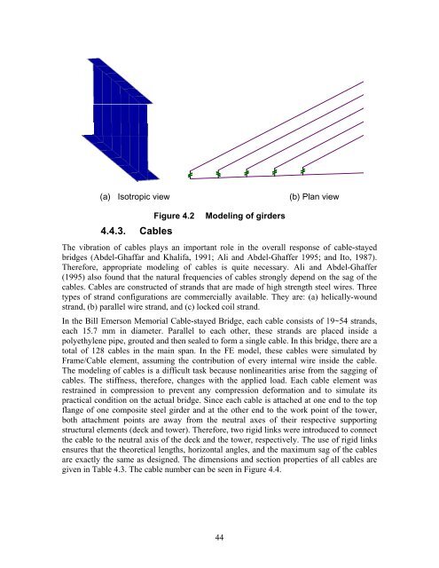
(a) Isotropic view(b) Plan view4.4.3. CablesFigure 4.2Modeling <strong>of</strong> girdersThe vibration <strong>of</strong> cables plays an important role in <strong>the</strong> overall response <strong>of</strong> cable-stayedbridges (Abdel-Ghaffar and Khalifa, 1991; Ali and Abdel-Ghaffer 1995; and Ito, 1987).Therefore, appropriate modeling <strong>of</strong> cables is quite necessary. Ali and Abdel-Ghaffer(1995) also found that <strong>the</strong> natural frequencies <strong>of</strong> cables strongly depend on <strong>the</strong> sag <strong>of</strong> <strong>the</strong>cables. Cables are constructed <strong>of</strong> strands that are made <strong>of</strong> high strength steel wires. Threetypes <strong>of</strong> strand configurations are commercially available. They are: (a) helically-woundstrand, (b) parallel wire strand, and (c) locked coil strand.In <strong>the</strong> <strong>Bill</strong> <strong>Emerson</strong> <strong>Memorial</strong> Cable-stayed <strong>Bridge</strong>, each cable consists <strong>of</strong> 19~54 strands,each 15.7 mm in diameter. Parallel to each o<strong>the</strong>r, <strong>the</strong>se strands are placed inside apolyethylene pipe, grouted and <strong>the</strong>n sealed to form a single cable. In this bridge, <strong>the</strong>re are atotal <strong>of</strong> 128 cables in <strong>the</strong> main span. In <strong>the</strong> FE model, <strong>the</strong>se cables were simulated byFrame/Cable element, assuming <strong>the</strong> contribution <strong>of</strong> every internal wire inside <strong>the</strong> cable.The modeling <strong>of</strong> cables is a difficult task because nonlinearities arise from <strong>the</strong> sagging <strong>of</strong>cables. The stiffness, <strong>the</strong>refore, changes with <strong>the</strong> applied load. Each cable element wasrestrained in compression to prevent any compression deformation and to simulate itspractical condition on <strong>the</strong> actual bridge. Since each cable is attached at one end to <strong>the</strong> topflange <strong>of</strong> one composite steel girder and at <strong>the</strong> o<strong>the</strong>r end to <strong>the</strong> work point <strong>of</strong> <strong>the</strong> tower,both attachment points are away from <strong>the</strong> neutral axes <strong>of</strong> <strong>the</strong>ir respective supportingstructural elements (deck and tower). Therefore, two rigid links were introduced to connect<strong>the</strong> cable to <strong>the</strong> neutral axis <strong>of</strong> <strong>the</strong> deck and <strong>the</strong> tower, respectively. The use <strong>of</strong> rigid linksensures that <strong>the</strong> <strong>the</strong>oretical lengths, horizontal angles, and <strong>the</strong> maximum sag <strong>of</strong> <strong>the</strong> cablesare exactly <strong>the</strong> same as designed. The dimensions and section properties <strong>of</strong> all cables aregiven in Table 4.3. The cable number can be seen in Figure 4.4.44


