

Assessment of the Bill Emerson Memorial Bridge - FTP Directory ...
Assessment of the Bill Emerson Memorial Bridge - FTP Directory ...
Assessment of the Bill Emerson Memorial Bridge - FTP Directory ...
- No tags were found...

You also want an ePaper? Increase the reach of your titles
YUMPU automatically turns print PDFs into web optimized ePapers that Google loves.
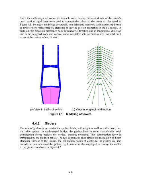
Since <strong>the</strong> cable stays are connected to each tower outside <strong>the</strong> neutral axis <strong>of</strong> <strong>the</strong> tower’scross section, rigid links were used to connect <strong>the</strong> cables to <strong>the</strong> tower as illustrated inFigure 4.1. To model <strong>the</strong> bridge accurately, non-prismatic members such as pier cap beamsor towers were represented by elements <strong>of</strong> varying section properties in <strong>the</strong> FE model. Inaddition, <strong>the</strong> elevation difference both in transverse direction and in longitudinal directiondue to <strong>the</strong> designed slope and vertical curve was taken into account as well. An infill wallexists at <strong>the</strong> bottom <strong>of</strong> each tower.(a) View in traffic directionFigure 4.1(b) View in longitudinal directionModeling <strong>of</strong> towers4.4.2. GirdersThe role <strong>of</strong> girders is to transfer <strong>the</strong> applied loads, self weight as well as traffic load, into<strong>the</strong> cable system. In cable-stayed bridge, <strong>the</strong> girders have to resist considerable axialcompression forces besides <strong>the</strong> vertical bending moments. This compression force isintroduced by <strong>the</strong> inclined cables. The two continuous edge girders are modeled with beamelements. Similar to <strong>the</strong> towers, <strong>the</strong> connection points <strong>of</strong> cables to <strong>the</strong> girders are alsooutside <strong>the</strong> neutral axis <strong>of</strong> <strong>the</strong> girders, rigid links were also employed to connect <strong>the</strong> cablesto <strong>the</strong> girders, as shown in Figure 4.2.43


