

Assessment of the Bill Emerson Memorial Bridge - FTP Directory ...
Assessment of the Bill Emerson Memorial Bridge - FTP Directory ...
Assessment of the Bill Emerson Memorial Bridge - FTP Directory ...
- No tags were found...

You also want an ePaper? Increase the reach of your titles
YUMPU automatically turns print PDFs into web optimized ePapers that Google loves.
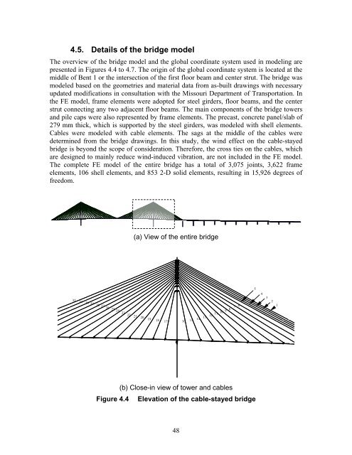
4.5. Details <strong>of</strong> <strong>the</strong> bridge modelThe overview <strong>of</strong> <strong>the</strong> bridge model and <strong>the</strong> global coordinate system used in modeling arepresented in Figures 4.4 to 4.7. The origin <strong>of</strong> <strong>the</strong> global coordinate system is located at <strong>the</strong>middle <strong>of</strong> Bent 1 or <strong>the</strong> intersection <strong>of</strong> <strong>the</strong> first floor beam and center strut. The bridge wasmodeled based on <strong>the</strong> geometries and material data from as-built drawings with necessaryupdated modifications in consultation with <strong>the</strong> Missouri Department <strong>of</strong> Transportation. In<strong>the</strong> FE model, frame elements were adopted for steel girders, floor beams, and <strong>the</strong> centerstrut connecting any two adjacent floor beams. The main components <strong>of</strong> <strong>the</strong> bridge towersand pile caps were also represented by frame elements. The precast, concrete panel/slab <strong>of</strong>279 mm thick, which is supported by <strong>the</strong> steel girders, was modeled with shell elements.Cables were modeled with cable elements. The sags at <strong>the</strong> middle <strong>of</strong> <strong>the</strong> cables weredetermined from <strong>the</strong> bridge drawings. In this study, <strong>the</strong> wind effect on <strong>the</strong> cable-stayedbridge is beyond <strong>the</strong> scope <strong>of</strong> consideration. Therefore, <strong>the</strong> cross ties on <strong>the</strong> cables, whichare designed to mainly reduce wind-induced vibration, are not included in <strong>the</strong> FE model.The complete FE model <strong>of</strong> <strong>the</strong> entire bridge has a total <strong>of</strong> 3,075 joints, 3,622 frameelements, 106 shell elements, and 853 2-D solid elements, resulting in 15,926 degrees <strong>of</strong>freedom.(a) View <strong>of</strong> <strong>the</strong> entire bridge32 31 30 29 28 27 26 25242322 21 2019 18 17 16 15543276 11110 98121413Figure 4.4(b) Close-in view <strong>of</strong> tower and cablesElevation <strong>of</strong> <strong>the</strong> cable-stayed bridge48


