

Assessment of the Bill Emerson Memorial Bridge - FTP Directory ...
Assessment of the Bill Emerson Memorial Bridge - FTP Directory ...
Assessment of the Bill Emerson Memorial Bridge - FTP Directory ...
- No tags were found...

You also want an ePaper? Increase the reach of your titles
YUMPU automatically turns print PDFs into web optimized ePapers that Google loves.
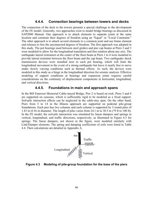
4.4.4. Connection bearings between towers and decksThe connection <strong>of</strong> <strong>the</strong> deck to <strong>the</strong> towers presents a special challenge to <strong>the</strong> development<strong>of</strong> <strong>the</strong> FE model. Generally, two approaches exist to model bridge bearings as discussed inSAP2000 Manual. One approach is to attach elements to separate joints at <strong>the</strong> samelocation and constrain <strong>the</strong>ir degrees <strong>of</strong> freedom using an “Equal” or “Local Constraint.”The o<strong>the</strong>r approach is to attach several elements to a common joint and use frame elementend releases to free <strong>the</strong> unconnected degrees <strong>of</strong> freedom. The first approach was adopted inthis study. The pot bearings used between steel girders and pier cap beams at Piers 2 and 3were modeled to allow for <strong>the</strong> longitudinal translation and free rotation about any axis. Theearthquake lateral restrainers at <strong>the</strong> center <strong>of</strong> <strong>the</strong> floor beam at Piers 1 to 4 were modeled toprovide lateral restraints between <strong>the</strong> floor beam and <strong>the</strong> cap beam. Two earthquake shocktransmission devices were installed next to each pot bearing, which will limit <strong>the</strong>longitudinal movement in <strong>the</strong> event <strong>of</strong> a strong earthquake but leave it nearly free to moveunder slowly varying conditions such as <strong>the</strong>rmal effects. As such, <strong>the</strong> devices weremodeled in this study as a hinge in <strong>the</strong> longitudinal direction for seismic analysis. Effectivemodeling <strong>of</strong> support conditions at bearings and expansion joints requires carefulconsiderations on <strong>the</strong> continuity <strong>of</strong> displacement components in horizontal, longitudinal,and vertical directions.4.4.5. Foundations in main and approach spansIn <strong>the</strong> <strong>Bill</strong> <strong>Emerson</strong> <strong>Memorial</strong> Cable-stayed <strong>Bridge</strong>, Pier 2 is based on rock. Piers 3 and 4are supported on caissons, which is sufficiently rigid to be modeled as a fixed support.Soil-pile interaction effects can be neglected in <strong>the</strong> cable-stay span. On <strong>the</strong> o<strong>the</strong>r hand,Piers from 5 to 14 in <strong>the</strong> Illinois approach are supported on pedestal pile-groupfoundations. Each pier has two columns and each column is supported by 5 round piles <strong>of</strong>1.83 m (6 ft) in diameter. The length <strong>of</strong> piles varies from 24.1 m to 30.5 m (79 ft to 100 ft).In <strong>the</strong> FE model, <strong>the</strong> soil-pile interaction was simulated by linear dampers and springs invertical, longitudinal, and traffic directions, respectively, as illustrated in Figure 4.3 forsprings. The linear dampers, not shown in <strong>the</strong> figure, were modeled similarly withLink/Damper elements. The spring and damping coefficients <strong>of</strong> soils were listed in Table4.4. Their calculations are detailed in Appendix A.TrafficLongitudinalVerticalFigure 4.3Modeling <strong>of</strong> pile-group foundation for <strong>the</strong> base <strong>of</strong> <strong>the</strong> piers46


