

Assessment of the Bill Emerson Memorial Bridge - FTP Directory ...
Assessment of the Bill Emerson Memorial Bridge - FTP Directory ...
Assessment of the Bill Emerson Memorial Bridge - FTP Directory ...
- No tags were found...

You also want an ePaper? Increase the reach of your titles
YUMPU automatically turns print PDFs into web optimized ePapers that Google loves.
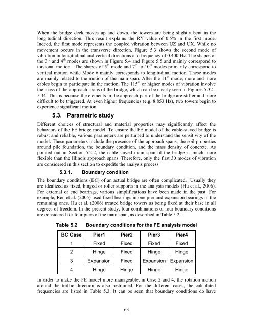
When <strong>the</strong> bridge deck moves up and down, <strong>the</strong> towers are being slightly bent in <strong>the</strong>longitudinal direction. This result explains <strong>the</strong> RY value <strong>of</strong> 0.5% in <strong>the</strong> first mode.Indeed, <strong>the</strong> first mode represents <strong>the</strong> coupled vibration between UZ and UX. While nomovement occurs in <strong>the</strong> transverse direction, Figure 5.3 shows <strong>the</strong> second mode <strong>of</strong>vibration in longitudinal and vertical directions at a frequency <strong>of</strong> 0.400 Hz. The shapes <strong>of</strong><strong>the</strong> 3 rd and 4 th modes are shown in Figure 5.4 and Figure 5.5 and mainly correspond totorsional motion. The shapes <strong>of</strong> 5 th mode and 7 th to 10 th modes primarily correspond tovertical motion while Mode 6 mainly corresponds to longitudinal motion. These modesare mainly related to <strong>the</strong> motion <strong>of</strong> <strong>the</strong> main span. After <strong>the</strong> 11 th mode, more and morecables begin to participate in <strong>the</strong> motion. The 115 th or higher modes <strong>of</strong> vibration involve<strong>the</strong> mass <strong>of</strong> <strong>the</strong> approach spans <strong>of</strong> <strong>the</strong> bridge, which can be clearly seen in Figures 5.32 -5.34. This is because <strong>the</strong> elements in <strong>the</strong> approach part <strong>of</strong> <strong>the</strong> bridge are stiffer and moredifficult to be triggered. At even higher frequencies (e.g. 8.853 Hz), two towers begin toexperience significant motion.5.3. Parametric studyDifferent choices <strong>of</strong> structural and material properties may significantly affect <strong>the</strong>behaviors <strong>of</strong> <strong>the</strong> FE bridge model. To ensure <strong>the</strong> FE model <strong>of</strong> <strong>the</strong> cable-stayed bridge isrobust and reliable, various parameters are perturbed to understand <strong>the</strong> sensitivity <strong>of</strong> <strong>the</strong>model. These parameters include <strong>the</strong> presence <strong>of</strong> <strong>the</strong> approach spans, <strong>the</strong> soil propertiesaround pile foundation, <strong>the</strong> boundary condition, and <strong>the</strong> mass density <strong>of</strong> concrete. Aspointed out in Section 5.2.2, <strong>the</strong> cable-stayed main span <strong>of</strong> <strong>the</strong> bridge is much moreflexible than <strong>the</strong> Illinois approach spans. Therefore, only <strong>the</strong> first 30 modes <strong>of</strong> vibrationare considered in this section to expedite <strong>the</strong> analysis process.5.3.1. Boundary conditionThe boundary conditions (BC) <strong>of</strong> an actual bridge are <strong>of</strong>ten complicated. Usually <strong>the</strong>yare idealized as fixed, hinged or roller supports in <strong>the</strong> analysis models (Hu et al., 2006).For external or end bearings, various simplifications have been made in <strong>the</strong> past. Forexample, Ren et al. (2005) used fixed bearings in one pier and expansion bearings in <strong>the</strong>remaining ones. Hu et al. (2006) treated bridge towers as being fixed at <strong>the</strong>ir base in alldegrees <strong>of</strong> freedom. In <strong>the</strong> present study, four combinations <strong>of</strong> four boundary conditionsare considered for four piers <strong>of</strong> <strong>the</strong> main span, as described in Table 5.2.Table 5.2Boundary conditions for <strong>the</strong> FE analysis modelBC Case Pier1 Pier2 Pier3 Pier41 Fixed Fixed Fixed Fixed2 Hinge Fixed Hinge Hinge3 Expansion Fixed Expansion Expansion4 Hinge Hinge Hinge HingeIn order to make <strong>the</strong> FE model more manageable, in Case 2 and 4, <strong>the</strong> rotation motionaround <strong>the</strong> traffic direction is also restrained. For <strong>the</strong> different cases, <strong>the</strong> calculatedfrequencies are listed in Table 5.3. It can be seen that boundary conditions do have63


