

920i Installation Manual V4.01 - Rice Lake Weighing Systems
920i Installation Manual V4.01 - Rice Lake Weighing Systems
920i Installation Manual V4.01 - Rice Lake Weighing Systems

You also want an ePaper? Increase the reach of your titles
YUMPU automatically turns print PDFs into web optimized ePapers that Google loves.
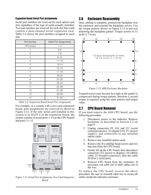
1Expansion Board Serial Port AssignmentsSerial port numbers are reserved for each option cardslot, regardless of the type of cards actually installed.Two port numbers are reserved for each slot that couldcontain a dual-channel serial expansion card.Table 2-6 shows the port numbers assigned to eachslot.Slot NumberSerial Port Assignments2.6 Enclosure ReassemblyOnce cabling is complete, position the backplate overthe enclosure and reinstall the backplate screws. Usethe torque pattern shown in Figure 2-13 to preventdistorting the backplate gasket. Torque screws to 15in-lb (1.7 N-m).16 1281018CPU board 1–41 5–62 7–83 9–104 11–125 13–146 15–167 17–188 19–209 21–2210 23–2411 25–2612 27–2813 29–3014 31–32Table 2-6. Expansion Board Serial Port AssignmentsFor example, in a system with a two-card expansionboard, port assignments are reserved as shown inFigure 2-12. If the only serial card installed in thissystem is in SLOT 4 of the expansion board, thesystem consists of serial ports 1–4 (on the CPU board)and ports 11–12.PORT2PORT1PORTS9–10SLOT 3 SLOT 4PORTS5–6SLOT 1 SLOT 2CPU BOARDPORT3PORT4PORTS11–12PORTS7–8SLOT 0Figure 2-12. Serial Port Assignments, Two-Card ExpansionBoard1453117Torque backplate screwsto 15 in-lb (1.7 N-m)97Figure 2-13. <strong>920i</strong> Enclosure BackplateTorqued screws may become less tight as the gasket iscompressed during torque pattern, therefore a secondtorque is required using the same pattern and torquevalue.2.7 CPU Board RemovalIf you must remove the <strong>920i</strong> CPU board, use thefollowing procedure:1. Disconnect power to the indicator. Removebackplate as described in Section 2.2 onpage 8.2. Unplug connectors J9, J10, and J11 (serialcommunications), J2 (digital I/O), P1 (powersupply), and connectors to any installedoption cards.3. Remove any installed option cards.4. Remove the five phillips head screws and twokep nuts from the CPU board.5. Gently lift up the CPU board, then disconnectconnectors J12 (power to display), J4 (ribboncable, J3 (keypad connector), then the cableJ8 (Port 2 serial port).6. Remove CPU board from the enclosure. Ifnecessary, cut cable ties to shift cables out ofthe way.To replace the CPU board, reverse the aboveprocedure. Be sure to reinstall cable ties to secure allcables inside the indicator enclosure.111513624<strong>Installation</strong> 15


