You also want an ePaper? Increase the reach of your titles
YUMPU automatically turns print PDFs into web optimized ePapers that Google loves.
Alloy steel valves are used in high-pressure,<br />
high-temperature systems; the disks and seats of these<br />
valves are usually surfaced with a chromium-cobalt<br />
alloy known as Stellite. This material is extremely hard.<br />
You will find information on the commonly used<br />
types of valves and their construction in Fireman,<br />
NAVEDTRA 12001. The information in the following<br />
sections applies to globe, ball, and gate valves, but the<br />
procedures can usually be adapted to repair any type of<br />
valve.<br />
Repairing Globe Valves<br />
Begin with an inspection of all parts of the valve for<br />
wear and alignment and, if you find them defective,<br />
repair or renew them. However, most valve repair is<br />
limited to overhaul of the seat and disk, and we will<br />
concentrate on those procedures.<br />
Make a close inspection of the valve seat and disk.<br />
Look for erosion, cuts on the seating area, and proper<br />
fit of the disk to its seat. In a normal overhaul, you will<br />
grind-in the seat and disk, or lap the seat and machine<br />
the disk in a lathe. When the parts are in such bad<br />
condition that the normal procedure will not work, you<br />
must machine both the valve disk and valve seat in a<br />
lathe. If the disk and seat appear to be in good condition,<br />
use the spotting-in procedure described in the next<br />
paragraphs to be sure.<br />
SPOTTING-IN.—Use this procedure to visually<br />
determine whether or not the seat or disk make good<br />
contact with each other. To spot-in a valve seat, first<br />
apply a thin coating of prussian blue evenly over the<br />
entire machined face surface of the disk. Next, insert the<br />
disk into the valve and rotate it a quarter turn, using a<br />
light downward force. The prussian blue will adhere to<br />
the valve seat at points where the disk makes contact.<br />
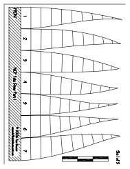
Figure 13-3 shows the patterns of prussian blue on a<br />
correct seat and on imperfect seats. After you have<br />
noted the condition of the seat surface, wipe all the<br />
prussian blue off of the disk face surface, then apply a<br />
thin, even coat on the contact face of the seat. Again<br />
place the disk on the valve seat and rotate the disk a<br />
quarter turn. Examine the resulting blue ring on the<br />
valve disk. If the ring is unbroken and of uniform width,<br />
and there are no cuts, scars, or irregularities on the face,<br />
the disk is in good condition. If the ring is broken or<br />
wavy, the disk is not making proper contact with the<br />
seat and must be machined.<br />
GRINDING.—Valve grinding is the method of<br />
removing small irregularities from the contact surfaces<br />
13-5<br />
Figure 13-3.—Examples of spotted-in valve seats.<br />
of the seat and disk. You also will use this process to on<br />
seats or disks you have machined.<br />
To grind-in a valve, apply a small amount of<br />
grinding compound to the face of the disk, insert the<br />
disk into the valve and rotate the disk back and forth<br />
about a quarter turn. Shift the disk-seat relation from<br />
time to time so the disk will be rotated gradually in<br />
increments through several rotations. The grinding<br />
compound will gradually be displaced from between the<br />
seat and disk surfaces, so you must stop every minute<br />
or so to replenish the compound. For best results when<br />
you replenish, wipe the old compound off the seat and<br />
the disk before you apply the new compound. When it<br />
appears that the irregularities have been removed,<br />
spot-in the disk to the seat as described previously.<br />
When you first spot-in a machined valve seat and<br />
disk, the scat contact will be very narrow and located<br />
close to the edge of the bore. Grinding-in, using finer<br />
compounds as the work progresses, causes the seat<br />
contact to become broader until it looks like the “correct<br />
seat” shown in figure 13-3. The contact area should be<br />
a perfect ring, covering approximately one-third of the<br />
seating surface.<br />
Avoid over-grinding. It will produce a groove in the<br />
seating surface of the disk and it may round off the<br />
straight angular surface of the seat. You will have to<br />
machine the surfaces to correct the effects of<br />
overgrinding.<br />
LAPPING.—Lapping serves the same purpose as<br />
grinding, but it works only on the valve seat and it<br />
removes slightly larger irregularities than grinding. In<br />
this procedure, you will use a cast-iron lapping tool that