- Page 1 and 2:
Naval Education and Training Comman
- Page 3 and 4:
MACHINERY REPAIRMAN NAVEDTRA 12204-
- Page 6 and 7:
PREFACE This Training Manual (TRAMA
- Page 8 and 9:
CONTENTS CHAPTER PAGE 1. 2. 3. 4. 5
- Page 10 and 11:
Another job description found in pr
- Page 12 and 13:
1-2, and 1-3 show some of the commo
- Page 14 and 15:
You must know the location of tools
- Page 16 and 17:
The correct way to measure an insid
- Page 18 and 19:
appropriate sides of the jaws on th
- Page 20 and 21:
Dial Bore Gauge The dial bore gauge
- Page 22 and 23:
Gear Tooth Vernier Use a gear tooth
- Page 24 and 25:
Surface Gauge A surface gauge (fig.
- Page 26 and 27:
Figure 1-20.—Center gauge. angle
- Page 28 and 29:
accuracy. They generally come in ma
- Page 30 and 31:
MICROMETERS is essentially the same
- Page 32 and 33:
meanings of these terms and the imp
- Page 34 and 35:
number is shown for roughness heigh
- Page 36 and 37:
Figure 2-7.—Master roughness scal
- Page 38 and 39:
Figure 2-11.—Checking surface fin
- Page 40 and 41:
Figure 2-17.—Laying out a 45-degr
- Page 42 and 43:
Figure 2-24.—Setting and using a
- Page 44 and 45:
Figure 2-29.—Bisecting an angle.
- Page 46 and 47:
prick-punch “witness marks” aro
- Page 48 and 49:
Figure 2-35.—Filing. The crosshat
- Page 50 and 51:
keyway broach requires a bushing th
- Page 52 and 53:
The steps involved in repairing a d
- Page 54 and 55:
SETTING UP OXYACETYLENE EQUIPMENT T
- Page 56 and 57:
GREASE IN THE PRESENCE OF OXYGEN UN
- Page 58 and 59:
Strength metal into thin sheets. Le
- Page 60 and 61:
and forming into plates, billets, b
- Page 62 and 63:
Each of the aluminum alloys has pro
- Page 64 and 65:
with an average carbon content of 1
- Page 66 and 67:
The manufacturer is required to mak
- Page 68 and 69:
with that of known specimens. Many
- Page 70 and 71:
Gray cast iron produces a spark str
- Page 72 and 73:
Table 3-4.—Major Groups of Plasti
- Page 74 and 75:
Lathe Operations Lathe operations a
- Page 76 and 77:
mechanism is also attached to the s
- Page 78 and 79:
Band Selection and Installation The
- Page 80 and 81:
File Bands A file band consists of
- Page 82 and 83:
This prevents sagging of the file b
- Page 84 and 85:
Figure 4-16.—Butt welder-grinder
- Page 86 and 87:
paragraphs contain the procedures f
- Page 88 and 89:
Figure 4-22.—Disk-cutting attachm
- Page 90 and 91:
Figure 4-26.—Sensitive drill pres
- Page 92 and 93:
shops are the Morse taper shank, sh
- Page 94 and 95:
Figure 4-30.—Common types of clam
- Page 96 and 97:
Figure 4-34.—Two types of counter
- Page 98 and 99:
andomly follow the straight sides a
- Page 101 and 102:
CHAPTER 5 OFFHAND GRINDING OF TOOLS
- Page 103 and 104:
Figure 5-4.—Standard marking syst
- Page 105 and 106:
DIAMOND WHEELS Diamond grinding whe
- Page 107 and 108:
WHEEL CARE AND STORAGE It’s easy
- Page 109 and 110:
allows cutting speeds approximately
- Page 111 and 112:
Figure 5-13.—Surface finish vs no
- Page 113 and 114:
Figure 5-17.—Boring bars for carb
- Page 115 and 116:
Figure 5-19.—Chip breakers. a rad
- Page 117 and 118:
Internal-threading tool: The intern
- Page 119 and 120:
Downcutting tool: You may grind and
- Page 121 and 122:
Figure 5-32.—Grinding drill lip c
- Page 123:
Figure 5-37.—Grinding a twist dri
- Page 126 and 127:
ways in alignment with the headstoc
- Page 128 and 129:
Figure 6-4 shows this plate for the
- Page 130 and 131:
Before you insert a center or tooli
- Page 132 and 133:
FEED ROD The feed rod transmits pow
- Page 134 and 135:
lower lever has eight positions, ea
- Page 136 and 137:
Figure 6-14.—Quick-change toolpos
- Page 138 and 139:
Figure 6-21.—Three-jaw universal
- Page 140 and 141:
Figure 6-26.—Cutaway showing the
- Page 142 and 143:
Figure 6-32.—Thread dial indicato
- Page 144 and 145:
TRACING ATTACHMENTS A tracing attac
- Page 146 and 147:
2. Place the level across the bed a
- Page 148 and 149:
Figure 6-41.—Aligning lathe cente
- Page 150 and 151:
Figure 6-45.—Boring center hole.
- Page 152 and 153:
ends of the mandrel when you press
- Page 154 and 155:
Figure 6-52.—Centering work with
- Page 156 and 157:
Figure 6-56.—Work mounted on a ca
- Page 158 and 159:
FEED is the amount the tool advance
- Page 160 and 161:
Rough Turning Figure 6-62.—Rough
- Page 162 and 163:
Square, round, and “V” grooves
- Page 164 and 165:
Figure 6-69.—Knurled impressions.
- Page 166 and 167:
machined surfaces that could become
- Page 168 and 169:
produced by the same amount of seto
- Page 170 and 171:
cross-feed screw and the cross-slid
- Page 172 and 173:
When special threads are required b
- Page 174 and 175:
Figure 6-83.—Acme thread and form
- Page 176 and 177:
where An example of a pipe thread i
- Page 178 and 179:
The wire size you should use to mea
- Page 180 and 181:
Using the Thread-Cutting Stop Becau
- Page 182 and 183:
Figure 6-96.—Finishing the end of
- Page 184 and 185:
shown in figure 6-101. Two slots ar
- Page 186 and 187:
Figure 7-1.—Universal milling mac
- Page 188 and 189:
A. Spindle G. Spindle speed selecto
- Page 190 and 191:
with a split clamp to the overarm a
- Page 192 and 193:
to the table of the milling machine
- Page 194 and 195:
that most index heads have a 40 to
- Page 196 and 197:
Rapid indexing is used when a large
- Page 198 and 199:
or one complete turn plus 36 holes
- Page 200 and 201:
allows you to index divisions from
- Page 202 and 203:
from the one in which the pin is in
- Page 204 and 205:
Figure 7-24.—Side milling cutter.
- Page 206 and 207:
A. B. C. D. E. Figure 7-32.—Doubl
- Page 208 and 209:
Figure 7-36.—Inserted tooth face
- Page 210 and 211:
Figure 7-43.—Sprocket wheel cutte
- Page 212 and 213:
Figure 7-48.—Stub arbor. or on th
- Page 214 and 215:
Figure 7-54.—Spring collet chuck
- Page 216 and 217:
Figure 7-56.—Face milling. FACE M
- Page 218 and 219:
11. 12. 13. 14. 15. 16. 17. 18. 19.
- Page 220 and 221:
A. Lock screw for dog D. End mill B
- Page 222 and 223:
8. 9. 10. 11. 12. 13. 14. 15. 16. 1
- Page 224 and 225:
11. 12. 13. 14. 15. 16. 17. 18. 19.
- Page 226 and 227:
Figure 7-71.—Visual alignment of
- Page 228 and 229:
machine table. You will hold the cu
- Page 230 and 231:
Figure 7-77.—Boring with a fly cu
- Page 232 and 233:
Figure 7-79.—Vertical milling att
- Page 234 and 235:
Table 7-2.—Surface Cutting Speeds
- Page 236 and 237:
Table 7-4 shows recommended chip lo
- Page 238 and 239:
Figure 8-2.—A 36-inch vertical tu
- Page 240 and 241:
28.194 Figure 8-3.—Refacing a val
- Page 242 and 243:
HORIZONTAL BORING MILL The horizont
- Page 244 and 245:
7. After you have tightened the mou
- Page 246 and 247:
The table can be power driven to pr
- Page 249 and 250:
CHAPTER 9 SHAPERS, PLANERS, AND ENG
- Page 251 and 252:
Figure 9-3.—Swiveled and tilted t
- Page 253 and 254:
extent in planer and shaper work To
- Page 255 and 256:
the cutting speeds and related mach
- Page 257 and 258:
Figure 9-10.—Internal keyway: A.
- Page 259 and 260:
7. 8. 9. 10. 11. 12. 13. 14. Replac
- Page 261 and 262:
or housing attached on one side of
- Page 263 and 264:
Figure 9-18.—Engraving machine. F
- Page 265 and 266:
CUTTER SPEEDS The speeds listed in
- Page 267 and 268:
can readily see it after grinding t
- Page 269 and 270:
Figure 9-29.—Using an indexing at
- Page 271:
Any further movement of the work wi
- Page 274 and 275:
Figure 10-1.—Grain depth of cut;
- Page 276 and 277:
To select the proper work speed, ta
- Page 278 and 279:
Figure 10-8.—Magnetic chuck used
- Page 280 and 281:
can do on a surface grinder. Use th
- Page 282 and 283:
for straight cylindrical grinding o
- Page 284 and 285:
Figure 10-15.—Typical tooth rest
- Page 286 and 287:
of the work. Raise or lower the whe
- Page 288 and 289:
Figure 10-23.—Staggered-tooth sid
- Page 290 and 291:
Figure 10-28.—Grinding the periph
- Page 292 and 293:
Once the teeth are uniform, they sh
- Page 294 and 295:
After you have honed out the inaccu
- Page 296 and 297:
MACHINES With the rapid development
- Page 298 and 299:
Figure 11-3.—Slant bed for CNC la
- Page 300 and 301: Figure 11-6.—A typical CNC contro
- Page 302 and 303: Figure 11-8.—Continuous-path angl
- Page 304 and 305: CHAPTER 12 METAL BUILDUP CHAPTER LE
- Page 306 and 307: Figure 12-1.—Typical installation
- Page 308 and 309: Figure 12-5.—A typical sandblaste
- Page 310 and 311: Clean, dry air is essential for pro
- Page 312 and 313: It can reduce the amount of masking
- Page 314 and 315: quality assurance function of the p
- Page 316 and 317: pass-fail. In our educational syste
- Page 318 and 319: straighten a shaft, however, always
- Page 320 and 321: Figure 13-4.—Lapping tools. has t
- Page 322 and 323: pipe in which the valve is installe
- Page 324 and 325: Figure 13-10.—Constant-pressure g
- Page 326 and 327: When you install the control valve
- Page 328 and 329: casing wearing rings, impeller wear
- Page 330 and 331: Figure 13-17.—Removing a broken b
- Page 332 and 333: Figure 13-23.—Metal disintegrator
- Page 334 and 335: Figure 13-25.—Portable boring bar
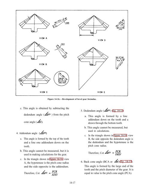
- Page 336 and 337: Figure 14-1.—Cutting specially sh
- Page 338 and 339: For example, use the following proc
- Page 340 and 341: at an angle to each other, as long
- Page 342 and 343: Figure 14-6.—Development of evenl
- Page 344 and 345: Table 14-1.—"K" Factor Table Tabl
- Page 346 and 347: Figure 14-11.—Standard universal
- Page 348 and 349: 6. Find the NPD. 7. Find the 8. Fin
- Page 352 and 353: 7. Pitch diameter (PD)—This is th
- Page 354 and 355: SELECTING A BEVEL GEAR CUTTER To cu
- Page 356 and 357: Figure 14-20.—Profiling a bevel g
- Page 358 and 359: . Use the following formulas to sol
- Page 360 and 361: Figure 14-25.—Milling machine set
- Page 362 and 363: 9. Diametral pitch (DP) METHOD OF M
- Page 364 and 365: explains the classes and the manufa
- Page 366 and 367: GRAINS (irregularly shaped crystals
- Page 368 and 369: Figure 15-2.—Microscopic structur
- Page 370 and 371: Figure 15-5.—Typical structure of
- Page 372 and 373: Figure 15-8.—Grid for heat-treati
- Page 374 and 375: Table 15-3.—Average Cooling Rates
- Page 376 and 377: cases. A wide variety of quenching
- Page 378 and 379: These various temperature arrests o
- Page 380 and 381: known as pearlite, and the A1 tempe
- Page 382 and 383: quickly cooled to and held at a som
- Page 384 and 385: Available information indicates tha
- Page 386 and 387: slowly from the tempering temperatu
- Page 388 and 389: Table 15-4.—Heat-Treating Tempera
- Page 390 and 391: Figure 15-20.—Design of a cam. A.
- Page 392 and 393: In carburized steel, spalling is ca
- Page 394 and 395: used to make positive identificatio
- Page 396 and 397: HONING—Finishing machine operatio
- Page 398 and 399: Table AII-2.—Decimal Equivalents
- Page 400 and 401:
Table AII-4.—Formulas for Dimensi
- Page 402 and 403:
Table AII-5.—Number, Letter and F
- Page 404 and 405:
Table AII-7.—Screw Thread and Tap
- Page 406 and 407:
Table AII-9.—3-Wire Method of Mea
- Page 408 and 409:
Table AII-11.—Circles Circumferen
- Page 410 and 411:
Table AII-13.—Taper Per Foot and
- Page 412 and 413:
p 1 I vi 2 P F \ = = a AII-16
- Page 414 and 415:
Table AII-16.—Drill Sizes for Tap
- Page 416 and 417:
Having Circular pitch Circular pitc
- Page 419 and 420:
APPENDIX IV DERIVATION OF FORMULAS
- Page 421:
(1) NT is the connecting link betwe
- Page 424 and 425:
Walker, John R., Machining Fundamen
- Page 427 and 428:
A Adjustable gauges, 1-7 adjustable
- Page 429 and 430:
Engine lathes, 6-1 attachments and
- Page 431 and 432:
Layout methods, 2-8 M forming angul
- Page 433 and 434:
Stub tooth gears, 14-27 American st