IM 01F06A00-01EN 14th Edition - Yokogawa
IM 01F06A00-01EN 14th Edition - Yokogawa
IM 01F06A00-01EN 14th Edition - Yokogawa
- No tags were found...

You also want an ePaper? Increase the reach of your titles
YUMPU automatically turns print PDFs into web optimized ePapers that Google loves.
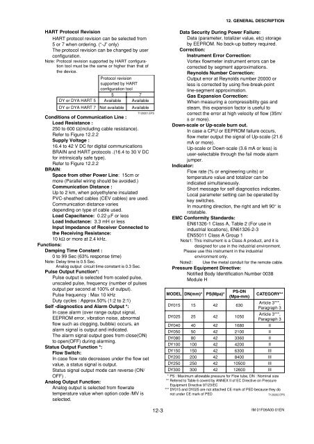
12. GENERAL DESCRIPTIONHART Protocol RevisionHART protocol revision can be selected from5 or 7 when ordering. (“-J” only)The protocol revision can be changed by userconfiguration.Note: Protocol revision supported by HART configurationtool must be the same or higher than that ofthe device.Protocol revisionsupported by HARTconfiguration tool5 7DY or DYA HART 5 Available AvailableDY or DYA HART 7 Not available AvailableT120201.EPSConditions of Communication Line :Load Resistance :250 to 600 Ω(including cable resistance).Refer to Figure 12.2.2Supply Voltage :16.4 to 42 V DC for digital communicationsBRAIN and HART protocols .(16.4 to 30 V DCfor intrinsically safe type).Refer to Figure 12.2.2BRAIN:Space from other Power Line: 15cm ormore (Parallel wiring should be avoided.)Communication Distance :Up to 2 km, when polyethylene insulatedPVC-sheathed cables (CEV cables) are used.Communication distance variesdepending on type of cable used.Load Capacitance: 0.22 µF or lessLoad Inductance: 3.3 mH or lessInput Impedance of Receiver Connected tothe Receiving Resistance:10 kΩ or more at 2.4 kHz.Functions:Damping Time Constant :0 to 99 Sec (63% response time)Note: Delay time is 0.5 Sec.Analog output circuit time constant is 0.3 Sec.Pulse Output Function*:Pulse output is selected from scaled pulse,unscaled pulse, frequency (number of pulsesoutput per second at 100% of output).Pulse frequency : Max 10 kHzDuty cycles : Approx.50% (1:2 to 2:1)Self -diagnostics and Alarm Output *:In case alarm (over range output signal,EEPROM error, vibration noise, abnormalflow such as clogging, bubble) occurs, analarm signal is output and indicated.The alarm signal output goes from close(ON)to open(OFF) during alarming.Status Output Function *:Flow Switch:In case flow rate decreases under the flow setvalue, a status signal is output.Status signal output mode can reverse (ON/OFF) .Analog Output Function:Analog output is selected from flowratetemperature value when option code /MV isselected.Data Security During Power Failure:Data (parameter, totalizer value, etc) storageby EEPROM. No back-up battery required.Correction:Instrument Error Correction:Vortex flowmeter instrument errors can becorrected by segment approximations.Reynolds Number Correction:Output error at Reynolds number 20000 orless is corrected by using five-break-pointline-segment approximation.Gas Expansion Correction:When measuring a compressibility gas andsteam, this expansion factor is useful tocorrect the error at high velocity of flow (35m/s or more).Down-scale or Up-scale burn out.In case a CPU or EEPROM failure occurs,flow meter output the signal of Up-scale (21.6mA or more).Up-scale or Down-scale (3.6 mA or less) isuser-selectable through the fail mode alarmjumper.Indicator:Flow rate (% or engineering units) ortemperature value and totalizer can beindicated simultaneously.Short message for self diagnostics indicates.Local parameter setting can be operated bykey switches.In mounting direction, the right and left 90° isrotatable.EMC Conformity Standards:EN61326-1 Class A, Table 2 (For use inindustrial locations), EN61326-2-3EN55011 Class A Group 1Note1: This instrument is a Class A product, and it isdesigned for use in the industrial environment.Please use this instrument in the industrialenvironment only.Note2: Use the metal conduit for the remote cable.Pressure Equipment Directive:Notified Body Identification Number 0038Module HMODELDY015DY025DY040DY050DY080DY100DY150DY200DY250DY300DN(mm)*1525405080100150200250300PS(Mpa)*42424242424242424242PS-DN(Mpa-mm)63010501680210033604200630084001050012600CATEGORY**Article 3***,Paragraph 3Article 3***,Paragraph 3IIIIIIIIIIIIIIIIIIII* PS : Maximum allowable pressure for Flow tube, DN : Nominal size** Refered to Table 6 coverd by ANNEX II of EC Directive on PressureEquipment Directive 97/23/EC*** DY015 and DY025 are not attached CE mark of PED because they donot under CE mark of PEDT120202.EPS12-3 <strong>IM</strong> <strong>01F06A00</strong>-<strong>01EN</strong>
![[MI 019-120] I/A Series Mass Flowtubes Models CFS20 ... - Invensys](https://img.yumpu.com/48832334/1/190x245/mi-019-120-i-a-series-mass-flowtubes-models-cfs20-invensys.jpg?quality=85)