IM 01F06A00-01EN 14th Edition - Yokogawa
IM 01F06A00-01EN 14th Edition - Yokogawa
IM 01F06A00-01EN 14th Edition - Yokogawa
- No tags were found...

Create successful ePaper yourself
Turn your PDF publications into a flip-book with our unique Google optimized e-Paper software.
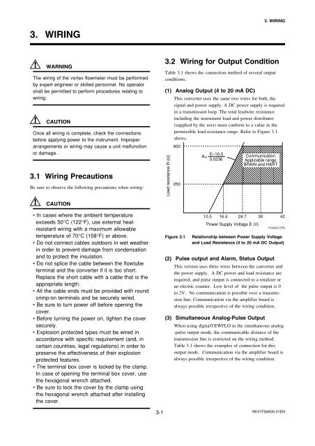
3. WIRING3. WIRINGWARNINGThe wiring of the vortex flowmeter must be performedby expert engineer or skilled personnel. No operatorshall be permitted to perform procedures relating towiring.CAUTIONOnce all wiring is complete, check the connectionsbefore applying power to the instrument. Improperarrangements or wiring may cause a unit malfunctionor damage.3.1 Wiring PrecautionsBe sure to observe the following precautions when wiring:3.2 Wiring for Output ConditionTable 3.1 shows the connection method of several outputconditions.(1) Analog Output (4 to 20 mA DC)This converter uses the same two wires for both, thesignal and power supply. A DC power supply is requiredin a transmission loop. The total leadwire resistanceincluding the instrument load and power distributor(supplied by the user) must conform to a value in thepermissible load resistance range. Refer to Figure 3.1shows.Load resistance R (Ω)600250R= E–10.50.0236CommunicationApplicable rangeBRAIN and HARTCAUTION• In cases where the ambient temperatureexceeds 50°C (122°F), use external heatresistantwiring with a maximum allowabletemperature of 70°C (158°F) or above.• Do not connect cables outdoors in wet weatherin order to prevent damage from condensationand to protect the insulation.• Do not splice the cable between the flowtubeterminal and the converter if it is too short.Replace the short cable with a cable that is theappropriate length.• All the cable ends must be provided with roundcrimp-on terminals and be securely wired.• Be sure to turn power off before opening thecover.• Before turning the power on, tighten the coversecurely.• Explosion protected types must be wired inaccordance with specific requirement (and, incertain countries, legal regulations) in order topreserve the effectiveness of their explosionprotected features.• The terminal box cover is locked by the clamp.In case of opening the terminal box cover, usethe hexagonal wrench attached.• Be sure to lock the cover by the clamp usingthe hexagonal wrench attached after installingthe cover.Figure 3.110.5 16.4 24.7 30 42Power Supply Voltage E (V)F030201.EPSRelationship between Power Supply Voltageand Load Resistance (4 to 20 mA DC Output)(2) Pulse output and Alarm, Status OutputThis version uses three wires between the converter andthe power supply. A DC power and load resistance arerequired, and pulse output is connected to a totalizer oran electric counter. Low level of the pulse output is 0to 2V. No communication is possible over a transmissionline. Communication via the amplifier board isalways possible irrespective of the wiring condition.(3) Simultaneous Analog-Pulse OutputWhen using digitalYEWFLO in the simultaneous analog-pulse output mode, the communicable distance of thetransmission line is restricted on the wiring method.Table 3.1 shows the examples of connection for thisoutput mode. Communication via the amplifier board isalways possible irrespective of the wiring condition.3-1 <strong>IM</strong> <strong>01F06A00</strong>-<strong>01EN</strong>


![[MI 019-120] I/A Series Mass Flowtubes Models CFS20 ... - Invensys](https://img.yumpu.com/48832334/1/190x245/mi-019-120-i-a-series-mass-flowtubes-models-cfs20-invensys.jpg?quality=85)