BROOKFIELD DV-II+ PROGRAMMABLE VISCOMETER Operating ...
BROOKFIELD DV-II+ PROGRAMMABLE VISCOMETER Operating ...
BROOKFIELD DV-II+ PROGRAMMABLE VISCOMETER Operating ...
Create successful ePaper yourself
Turn your PDF publications into a flip-book with our unique Google optimized e-Paper software.
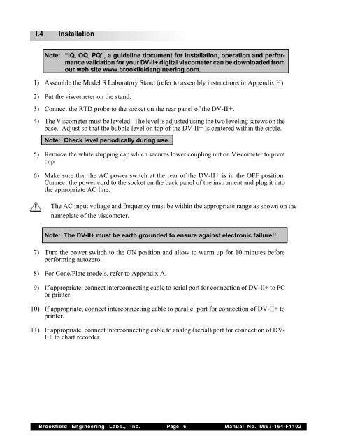
I.4 InstallationNote: “IQ, OQ, PQ”, a guideline document for installation, operation and performancevalidation for your <strong>DV</strong>-<strong>II+</strong> digital viscometer can be downloaded fromour web site www.brookfieldengineering.com.1) Assemble the Model S Laboratory Stand (refer to assembly instructions in Appendix H).2) Put the viscometer on the stand.3) Connect the RTD probe to the socket on the rear panel of the <strong>DV</strong>-<strong>II+</strong>.4) The Viscometer must be leveled. The level is adjusted using the two leveling screws on thebase. Adjust so that the bubble level on top of the <strong>DV</strong>-<strong>II+</strong> is centered within the circle.Note: Check level periodically during use.5) Remove the white shipping cap which secures lower coupling nut on Viscometer to pivotcup.6) Make sure that the AC power switch at the rear of the <strong>DV</strong>-<strong>II+</strong> is in the OFF position.Connect the power cord to the socket on the back panel of the instrument and plug it intothe appropriate AC line.The AC input voltage and frequency must be within the appropriate range as shown on thenameplate of the viscometer.Note: The <strong>DV</strong>-<strong>II+</strong> must be earth grounded to ensure against electronic failure!!7) Turn the power switch to the ON position and allow to warm up for 10 minutes beforeperforming autozero.8) For Cone/Plate models, refer to Appendix A.9) If appropriate, connect interconnecting cable to serial port for connection of <strong>DV</strong>-<strong>II+</strong> to PCor printer.10) If appropriate, connect interconnecting cable to parallel port for connection of <strong>DV</strong>-<strong>II+</strong> toprinter.11) If appropriate, connect interconnecting cable to analog (serial) port for connection of <strong>DV</strong>-<strong>II+</strong> to chart recorder.Brookfield Engineering Labs., Inc. Page 6 Manual No. M/97-164-F1102


