Gigabit QAM Modulator Model D9479 Hardware Installation and ...
Gigabit QAM Modulator Model D9479 Hardware Installation and ...
Gigabit QAM Modulator Model D9479 Hardware Installation and ...
- No tags were found...

You also want an ePaper? Increase the reach of your titles
YUMPU automatically turns print PDFs into web optimized ePapers that Google loves.
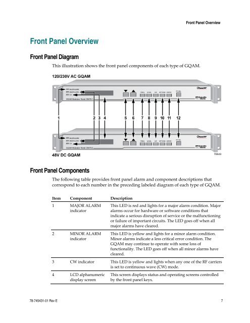
Front Panel OverviewFront Panel OverviewFront Panel DiagramThis illustration shows the front panel components of each type of G<strong>QAM</strong>.Front Panel ComponentsThe following table provides front panel alarm <strong>and</strong> component descriptions thatcorrespond to each number in the preceding labeled diagram of each type of G<strong>QAM</strong>.Item Component Description1 MAJOR ALARMindicator2 MINOR ALARMindicatorThis LED is red <strong>and</strong> lights for a major alarm condition. Majoralarms occur for hardware or software conditions thatindicate a serious disruption of service or the malfunctioningor failure of important circuits. The LED goes off when allmajor alarms have cleared.This LED is yellow <strong>and</strong> lights for a minor alarm condition.Minor alarms indicate a less critical error condition. TheG<strong>QAM</strong> may continue to operate with some loss offunctionality. The LED goes off when all minor alarms havecleared.3 CW indicator This LED is yellow <strong>and</strong> lights when any one of the RF carriersis set to continuous wave (CW) mode.4 LCD alphanumericdisplay screenThis screen displays status <strong>and</strong> operating screens controlledby the front panel keys.78-745431-01 Rev E 7