SIGNAL INTEGRITYBY howard johnson, phdpredict the size of a reflected signal:Why reflections happenThrow a rubber ball hard against a concrete wall. The ballbounces. You have just experienced a reflection. Reflectionshappen in propagating systems at those points where theconditions of propagation change.The best way to understand reflections is to track themovement of energy. When the ball reaches the wall, itcannot continue on its original course. Neither can the ball simply stop,because the energy associated with its incoming path cannot just disappear;it must go somewhere.Nature solves this problem by dividingthe incoming energy among theavailable outgoing modes of propagation.Those modes include the ball’sretreating along its incoming direction,an acoustic wave (bonk!) generated inthe air, a slight movement of the concretewall, and a residual thermal agitationof both rubber and concrete.The proportions of energy containedin each outgoing mode are determinedby the law of conservation of momentumin combination with the variousproperties, called boundary conditions,of each individual outgoing mode. Thereflecting-ball problem is tricky, becausethe ball can arrive at any incidentangle, it can carry spin, and there areINCOMINGENERGYREFLECTEDENERGYmultiple avenues for energy dissipation.A transmission line supports onlytwo modes of operation: A signal eithergoes straight down the line in one directionor comes back in the other. That’sit. In a typical digital application, noother modes of operation are possible.When a traveling wave encounters aload at the end of a transmission structure,only three entities are involved:the incoming power, the fraction ofthat power that is dissipated in the load,and the remaining power, all of whichreflects back toward the source.The solution to the problem ofallocating power among those threemodes is the highly vaunted “reflectioncoefficient” formula, which is used toCONCRETEWALLFigure 1 The wall converts a portion of the incoming energy into sound, heat,and vibration.SOUND,HEAT,ANDVIBRATIONV= Z –Z R L C.V IZ L+Z CThe reflection formula expresses theratio of reflected voltage to incidentvoltage, as observed at the end of atransmission line, computed as a functionof the load impedance at the end,Z L, and the characteristic impedance ofthe transmission line, Z C.If the end of a transmission structureis left open-circuited, making an infiniteload impedance, that load drawsno current and therefore dissipates zeropower. In that case, 100% of the incidentpower reflects, creating a reflectedsignal just as large as the incident waveform.If you imagine electrical currentas being loosely analogous to physicalvelocity in the rubber-ball example,the concrete wall did the same thing.When struck, the wall hardly moved,absorbing very little energy, and therebyreflecting almost perfectly.If you reduce the endpoint loadimpedance to successively lower values,the load begins to draw more current,dissipating more power and creating aprogressively weaker reflected signal. Inthe physical world, you can test that ideaby throwing your ball at three things: awooden fence, a wall of hay bales, anda wet sheet hanging out to dry. Whenthe mechanical impedance of the wallbest matches the physical properties ofthe ball, the ball reflects least strongly.Electrically, a load impedance thatcompletely absorbs all incoming powercreates zero reflection. That is the idealarrangement for an end terminator.That particular impedance, if you canfind it, is defined as the characteristicimpedance of the transmission structure.There is no other definition. Allformulas for characteristic impedanceare merely approximations of this ultimatemeaning.EDNHoward Johnson, PhD, of Signal Consulting,frequently conducts technical workshopsfor digital engineers at Oxford Universityand other sites worldwide. Visit hisWeb site at www.sigcon.com, or e-mail himat howie03@sigcon.com.20 EDN | MAY <strong>2013</strong> [ www.edn.com]
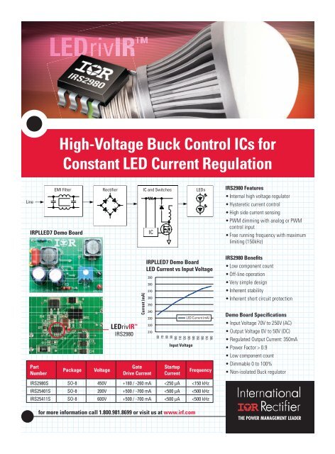
LEDrivIRHigh-Voltage Buck Control ICs forConstant LED Current RegulationLineEMI FilterIRPLLED7 Demo BoardRectifier IC and Switches LEDsICIRS2980 Features• Internal high voltage regulator• Hysteretic current control• High side current sensing• PWM dimming with analog or PWMcontrol input• Free running frequency with maximumlimiting (150kHz)LEDrivIR IRS2980Current (mA)IRPLLED7 Demo BoardLED Current vs Input Voltage3903803703603503403303203106<strong>07</strong><strong>08</strong>090100<strong>11</strong>01<strong>2013</strong>0140150160170180Input VoltageLED Current (mA)IRS2980 Benefits• Low component count• Off-line operation• Very simple design• Inherent stability• Inherent short circuit protectionDemo Board Specifications• Input Voltage 70V to 250V (AC)• Output Voltage 0V to 50V (DC)• Regulated Output Current: 350mA• Power Factor > 0.9• Low component countPartNumberPackageVoltageGateDrive CurrentStartupCurrentFrequency• Dimmable 0 to 100%• Non-isolated Buck regulatorIRS2980S SO-8 450V +180 / -260 mA


![[270].pdf 37407KB Sep 02 2010 09:55:57 AM - ElectronicsAndBooks](https://img.yumpu.com/50350834/1/185x260/270pdf-37407kb-sep-02-2010-095557-am-electronicsandbooks.jpg?quality=85)
![draaien, A Viruly 1935 OCR c20130324 [320]. - ElectronicsAndBooks](https://img.yumpu.com/49957773/1/190x252/draaien-a-viruly-1935-ocr-c20130324-320-electronicsandbooks.jpg?quality=85)


![20051110 c20051031 [105].pdf 35001KB Feb 18 2009 08:46:32 PM](https://img.yumpu.com/48687202/1/190x253/20051110-c20051031-105pdf-35001kb-feb-18-2009-084632-pm.jpg?quality=85)


