

201305.pdf 43279KB May 08 2013 11:07:04 PM
201305.pdf 43279KB May 08 2013 11:07:04 PM
201305.pdf 43279KB May 08 2013 11:07:04 PM

Create successful ePaper yourself
Turn your PDF publications into a flip-book with our unique Google optimized e-Paper software.
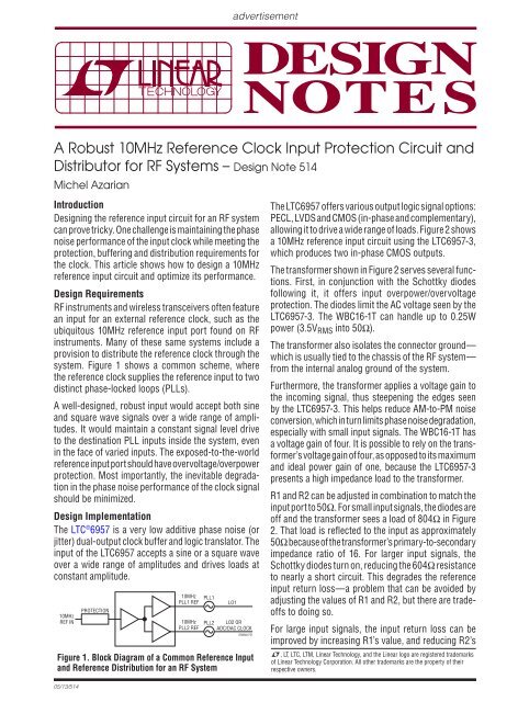
advertisementA Robust 10MHz Reference Clock Input Protection Circuit andDistributor for RF Systems – Design Note 514Michel AzarianIntroductionDesigning the reference input circuit for an RF systemcan prove tricky. One challenge is maintaining the phasenoise performance of the input clock while meeting theprotection, buffering and distribution requirements forthe clock. This article shows how to design a 10MHzreference input circuit and optimize its performance.Design RequirementsRF instruments and wireless transceivers often featurean input for an external reference clock, such as theubiquitous 10MHz reference input port found on RFinstruments. Many of these same systems include aprovision to distribute the reference clock through thesystem. Figure 1 shows a common scheme, wherethe reference clock supplies the reference input to twodistinct phase-locked loops (PLLs).A well-designed, robust input would accept both sineand square wave signals over a wide range of amplitudes.It would maintain a constant signal level driveto the destination PLL inputs inside the system, evenin the face of varied inputs. The exposed-to-the-worldreference input port should have overvoltage/overpowerprotection. Most importantly, the inevitable degradationin the phase noise performance of the clock signalshould be minimized.Design ImplementationThe LTC ® 6957 is a very low additive phase noise (orjitter) dual-output clock buffer and logic translator. Theinput of the LTC6957 accepts a sine or a square waveover a wide range of amplitudes and drives loads atconstant amplitude.10MHzREF INPROTECTION10MHzPLL1 REF10MHzPLL2 REFPLL1PLL2Figure 1. Block Diagram of a Common Reference Inputand Reference Distribution for an RF SystemLO1LO2 ORADC/DAC CLOCKDN4MA F01The LTC6957 offers various output logic signal options:PECL, LVDS and CMOS (in-phase and complementary),allowing it to drive a wide range of loads. Figure 2 showsa 10MHz reference input circuit using the LTC6957-3,which produces two in-phase CMOS outputs.The transformer shown in Figure 2 serves several functions.First, in conjunction with the Schottky diodesfollowing it, it offers input overpower/overvoltageprotection. The diodes limit the AC voltage seen by theLTC6957-3. The WBC16-1T can handle up to 0.25Wpower (3.5V RMS into 50Ω).The transformer also isolates the connector ground—which is usually tied to the chassis of the RF system—from the internal analog ground of the system.Furthermore, the transformer applies a voltage gain tothe incoming signal, thus steepening the edges seenby the LTC6957-3. This helps reduce AM-to-<strong>PM</strong> noiseconversion, which in turn limits phase noise degradation,especially with small input signals. The WBC16‐1T hasa voltage gain of four. It is possible to rely on the transformer’svoltage gain of four, as opposed to its maximumand ideal power gain of one, because the LTC6957-3presents a high impedance load to the transformer.R1 and R2 can be adjusted in combination to match theinput port to 50Ω. For small input signals, the diodes areoff and the transformer sees a load of 8<strong>04</strong>Ω in Figure2. That load is reflected to the input as approximately50Ω because of the transformer’s primary-to-secondaryimpedance ratio of 16. For larger input signals, theSchottky diodes turn on, reducing the 6<strong>04</strong>Ω resistanceto nearly a short circuit. This degrades the referenceinput return loss—a problem that can be avoided byadjusting the values of R1 and R2, but there are tradeoffsto doing so.For large input signals, the input return loss can beimproved by increasing R1’s value, and reducing R2’sL, LT, LTC, LTM, Linear Technology, and the Linear logo are registered trademarksof Linear Technology Corporation. All other trademarks are the property of theirrespective owners.05/13/514


![[270].pdf 37407KB Sep 02 2010 09:55:57 AM - ElectronicsAndBooks](https://img.yumpu.com/50350834/1/185x260/270pdf-37407kb-sep-02-2010-095557-am-electronicsandbooks.jpg?quality=85)
![draaien, A Viruly 1935 OCR c20130324 [320]. - ElectronicsAndBooks](https://img.yumpu.com/49957773/1/190x252/draaien-a-viruly-1935-ocr-c20130324-320-electronicsandbooks.jpg?quality=85)


![20051110 c20051031 [105].pdf 35001KB Feb 18 2009 08:46:32 PM](https://img.yumpu.com/48687202/1/190x253/20051110-c20051031-105pdf-35001kb-feb-18-2009-084632-pm.jpg?quality=85)


