

201305.pdf 43279KB May 08 2013 11:07:04 PM
201305.pdf 43279KB May 08 2013 11:07:04 PM
201305.pdf 43279KB May 08 2013 11:07:04 PM

Create successful ePaper yourself
Turn your PDF publications into a flip-book with our unique Google optimized e-Paper software.
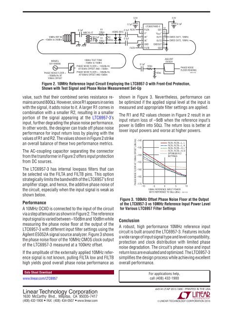
3.3V3.3V10MHz REF IN–10dBm to 24dBm0.1µFWBC16-1TR<strong>11</strong>00Ω0.1µF R<strong>11</strong>00ΩR26<strong>04</strong>Ω0.1µF0.1µF FILTAHSMS-281C0.1µFFILTBLTC6957HMS-3<strong>11</strong>2FILTA SD12V +<strong>11</strong>V+ OUT3IN +10OUT14IN –9OUT258GND GNDOUT67FILTB SD20.1µFCMOS OUT1, 10MHzCMOS OUT2, 10MHzWENZEL501-<strong>04</strong>6<strong>08</strong>APHASE NOISE FLOOR =–169dBc/Hz AT100kHz OFFSET10MHz TEST TONE–10dBm to 10dBmPHASE NOISE FLOOR = –163dBc/HzAT100kHz OFFSET AND –10dBmPHASE NOISE FLOOR = –169dBc/HzAT100kHz OFFSET AND 10dBm100Ω100ΩAGILENTE5052APHASE NOISEFLOOR READINGFigure 2. 10MHz Reference Input Circuit Employing the LTC6957-3 with Front-End Protection,Shown with Test Signal and Phase Noise Measurement Set-Up0.1µFDN514 F02value, such that their combined series resistance remainsaround 800Ω. However, since R1 appears in serieswith the signal, it adds noise to it. A larger R1 comes incombination with a smaller R2, resulting in a smallerportion of the signal appearing at the LTC6957-3’sinput, further degrading the phase noise performance.In other words, the designer can trade off phase noiseperformance for input return loss by playing with thevalues of R1 and R2. The values shown in Figure 2 strikean overall balance of these two performance metrics.The AC-coupling capacitor separating the connectorfrom the transformer in Figure 2 offers input protectionfrom DC sources.The LTC6957-3 has internal lowpass filters that canbe selected via the FILTA and FILTB pins. This optionstrategically limits the bandwidth of the LTC6957’s firstamplifier stage, and hence, the additive phase noise ofthe circuit, especially when the input signal is weak asshown below.PerformanceA 10MHz OCXO is connected to the input of the circuitvia a step attenuator as shown in Figure 2. The referenceinput signal is varied between –10dBm and 10dBm whilemeasuring the phase noise floor at the output of theLTC6957-3 with different input filter settings using theAgilent E5052A signal source analyzer. Figure 3 showsthe phase noise floor of the 10MHz CMOS clock outputof the LTC6957-3 measured at a 100kHz offset.If the amplitude of the externally applied 10MHz referencesignal is not known, pulling FILTA low and FILTBhigh yields good overall phase noise performance asData Sheet Downloadwww.linear.com/LTC6957shown in Figure 3. Nevertheless, performance canbe optimized if the applied signal level at the input ismeasured and appropriate filter settings are applied.The R1 and R2 values chosen in Figure 2 result in aninput return loss of –9dB when the reference input’spower is 0dBm into 50Ω. The return loss is better atlower input powers and worse at higher powers.PHASE NOISE FLOOR AT 100kHz OFFSET (dBc/Hz)–140–145–150–155–160–165–170–10FILTA, FILTB = L, LFILTA, FILTB = L, HFILTA, FILTB = H, LFILTA, FILTB = H, HOPTIMUM FILTSETTINGS–5 0 5 1010MHz REFERENCE INPUT POWERWITH REFERENCE TO 50Ω (dBm) DN514 F03Figure 3. 100kHz Offset Phase Noise Floor at the Outputof the LTC6957-3 vs 10MHz Reference Input Power Levelfor Various LTC6957 Filter SettingsConclusionA robust, high performance 10MHz reference inputcircuit is built around the LTC6957-3. Features includea wide range of input signal type and level compatibility,protection and clock distribution with limited phasenoise degradation. The circuit’s phase noise and inputreturn loss are evaluated and optimized. The LTC6957-3simplifies the design process while achieving excellentoverall performance.For applications help,call (4<strong>08</strong>) 432-1900Linear Technology Corporation1630 McCarthy Blvd., Milpitas, CA 95035-7417(4<strong>08</strong>) 432-1900 ● FAX: (4<strong>08</strong>) 434-05<strong>07</strong> ● www.linear.comdn514f LT/AP 0513 196K • PRINTED IN THE USA© LINEAR TECHNOLOGY CORPORATION <strong>2013</strong>


![[270].pdf 37407KB Sep 02 2010 09:55:57 AM - ElectronicsAndBooks](https://img.yumpu.com/50350834/1/185x260/270pdf-37407kb-sep-02-2010-095557-am-electronicsandbooks.jpg?quality=85)
![draaien, A Viruly 1935 OCR c20130324 [320]. - ElectronicsAndBooks](https://img.yumpu.com/49957773/1/190x252/draaien-a-viruly-1935-ocr-c20130324-320-electronicsandbooks.jpg?quality=85)


![20051110 c20051031 [105].pdf 35001KB Feb 18 2009 08:46:32 PM](https://img.yumpu.com/48687202/1/190x253/20051110-c20051031-105pdf-35001kb-feb-18-2009-084632-pm.jpg?quality=85)


