

201305.pdf 43279KB May 08 2013 11:07:04 PM
201305.pdf 43279KB May 08 2013 11:07:04 PM
201305.pdf 43279KB May 08 2013 11:07:04 PM

You also want an ePaper? Increase the reach of your titles
YUMPU automatically turns print PDFs into web optimized ePapers that Google loves.
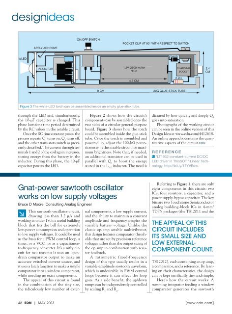
designideasAPPLY ADHESIVEON/OFF SWITCHPOCKET CLIP AT 90° WITH RESPECT TO SWITCHWLED1N40<strong>07</strong>INDUCTOR+1.2V, 2500-mAhr−NiCdCHARGINGSOCKET2.4CM4.3 CM2.2Ω9 CM20G GLUE-STICK TUBEFigure 3 The white-LED torch can be assembled inside an empty glue-stick tube.through the LED and, simultaneously,the 10-μF capacitor is charged. Thisphase lasts for a time period determinedby the RC values in the astable circuit.Once the RC time constant passes, theprocess repeats: Q 1turns on, Q 2turns off,and the other transistors switch as previouslydescribed. The current through terminals1 and 2 of the coil again increases,storing energy from the battery in theinductor. During this phase, the 10-μFcapacitor powers the LED.Figure 2 shows how the circuit’scomponents can be assembled onto thetwo sides of a circular general-purposeboard. Figure 3 shows how the torchcould be assembled inside the glue-sticktube. Once the torch is assembled andpowered up, adjust the 100-kΩ potentiometerin the astable circuit for maximumbrightness. Note that, if needed,an additional transistor can be used inparallel with Q 3to boost the energystored in the L 1-2inductor. The need isdictated by how quickly and deeply Q 3goes into saturation.Photographs of the working circuitcan be seen in the online version of thisDesign Idea at www.edn.com/4412618.An online appendix contains the quantitativeaspects of the circuit.EDNRefeR ence1 “LT1932 constant-current DC/DCLED driver in ThinSOT,” Linear Technology,http://bit.ly/17YVEdw.Gnat-power sawtooth oscillatorworks on low supply voltagesBruce D Moore, Consulting Analog Engineer↘This sawtooth-oscillator circuit,drawing less than 3.2 μA andworking at under 1V, is a useful buildingblock that fits the bill for extremelylow-power consumption and operationto low supply voltages. It could be usedas the basis for a PWM control loop, atimer, or a VCO, or as a capacitanceto-frequencyconverter. It’s a nifty circuitfor two reasons: It uses an opendraincomparator output to make anaccurate switched current source, andit uses a latch function to make a simplecomparator into a window comparator,while needing no extra components.The appeal of this circuit is foundin the combination of the tiny size,the ridiculously low number of externalcomponents, a low supply current,and the ability to maintain a constantamplitude and frequency despite thevariable battery voltage. Unlike theclassic op-amp astable multivibrator,this design features comparator thresholdsthat are set by precision referencevoltages rather than the output swing ofthe op amp in combination with resistorfeedback.A ratiometric fixed-frequencydesign of this type usually results in avariable-amplitude sawtooth waveform,which is undesirable in PWM controlloops because it can affect the loopgain. As a side benefit, the up/downramps can be independently controlledby scaling R 1and R 2.Referring to Figure 1, there are onlyeight components in this circuit: twoICs, four resistors, a capacitor, and apower-supply-bypass capacitor. The keybits are two Touchstone Semiconductoranalog building-block ICs in 4-mm 2TDFN packages (the TS120<strong>11</strong> and theThe appeal of ThiscircuiT includesiTs small size andlow exTernalcomponenTcounT.TS12012), each containing an op amp,a comparator, and a reference. By leaningon their characteristics, the designcan be kept terrifically tiny and simple.Here’s how the circuit works: Asumming integrator feeding a windowcomparator generates the sawtooth48 EDN | MAY <strong>2013</strong> [ www.edn.com]


![[270].pdf 37407KB Sep 02 2010 09:55:57 AM - ElectronicsAndBooks](https://img.yumpu.com/50350834/1/185x260/270pdf-37407kb-sep-02-2010-095557-am-electronicsandbooks.jpg?quality=85)
![draaien, A Viruly 1935 OCR c20130324 [320]. - ElectronicsAndBooks](https://img.yumpu.com/49957773/1/190x252/draaien-a-viruly-1935-ocr-c20130324-320-electronicsandbooks.jpg?quality=85)


![20051110 c20051031 [105].pdf 35001KB Feb 18 2009 08:46:32 PM](https://img.yumpu.com/48687202/1/190x253/20051110-c20051031-105pdf-35001kb-feb-18-2009-084632-pm.jpg?quality=85)


