

201305.pdf 43279KB May 08 2013 11:07:04 PM
201305.pdf 43279KB May 08 2013 11:07:04 PM
201305.pdf 43279KB May 08 2013 11:07:04 PM

Create successful ePaper yourself
Turn your PDF publications into a flip-book with our unique Google optimized e-Paper software.
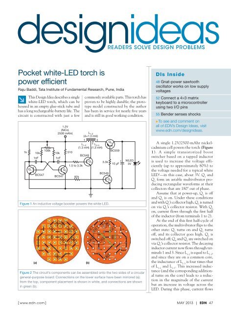
designideasreaderS SOLVe deSIGN PrOBLeMSPocket white-LED torch ispower efficientRaju Baddi, Tata Institute of Fundamental Research, Pune, India↘This Design Idea describes a singlewhite-LED torch, which can behoused in an empty glue-stick tube andhas a long rechargeable-battery life. Thecircuit is constructed with just a fewcommonly available parts. This torch hasproven to be highly durable; the prototypemodel constructed by the authorhas been in service for nearly five yearsand is still in good working condition.Q 51.2V(NiCd,2500 mAhr)+L 1-3(4×1.3 mH)1 3L 1-22 L 2-3Q 1 Q 2(1.3 mH) (1.3 mH)100kBC5591k 10k10k 510BC5491nF1nFQ 3 3.3k+10 μF1.5 to 3.3kBC549BC547BC547 82kQ 4Figure 1 An inductive voltage booster powers the white LED.(a)Figure 2 The circuit’s components can be assembled onto the two sides of a circulargeneral-purpose board: Connections on the lower surface have been mirrored (a);EDNDI5267 Fig 1.eps DIANEfrom the top, component placement is shown in white, and connections are shownin green (b).(b)WLED3VDIs Inside48 Gnat-power sawtoothoscillator works on low supplyvoltages52 Connect a 4×3 matrixkeyboard to a microcontrollerusing two I/O pins55 Bender senses shocks▶To see and comment onall of EDN’s Design Ideas, visitwww.edn.com/designideas.A single 1.2V/2500-mAhr nickelcadmiumcell powers the torch (Figure1). A simple transistorized boostswitcher based on a tapped inductoris used to increase the voltage efficiently(up to approximately 80%) tothe voltage needed for a typical whiteLED 1 —in this case, about 3V. Q 1andQ 2form an astable multivibrator producingrectangular waveforms at theircollectors that are 180° out of phase.Assume that at power-up, Q 2is offand Q 1is on. Under these conditionsand with Q 2’s collector high, Q 3is turnedon via Q 2’s collector resistor. With Q 3on, current flows through the first halfof the inductor (from terminals 1 to 2).At the end of this first half-cycle ofoperation, the multivibrator flips to theother state: Q 2turns on and Q 1turnsoff, and its collector goes high. Q 3isswitched off; Q 4and Q 5are switched onvia Q 1’s collector resistor. The decayinginductor current now flows through terminals1 and 3. Since L 1-2is equal to L 2-3,and since they are on a common core,the inductance of L 1-3is four times thatof L 1-2and L 2-3. This increased inductance(and the corresponding additionalturns on the core) leads to a reductionin the magnitude of the currentbut an increase in voltage across theLED. During this phase, current flows[ www.edn.com]<strong>May</strong> <strong>2013</strong> | EDN 47


![[270].pdf 37407KB Sep 02 2010 09:55:57 AM - ElectronicsAndBooks](https://img.yumpu.com/50350834/1/185x260/270pdf-37407kb-sep-02-2010-095557-am-electronicsandbooks.jpg?quality=85)
![draaien, A Viruly 1935 OCR c20130324 [320]. - ElectronicsAndBooks](https://img.yumpu.com/49957773/1/190x252/draaien-a-viruly-1935-ocr-c20130324-320-electronicsandbooks.jpg?quality=85)


![20051110 c20051031 [105].pdf 35001KB Feb 18 2009 08:46:32 PM](https://img.yumpu.com/48687202/1/190x253/20051110-c20051031-105pdf-35001kb-feb-18-2009-084632-pm.jpg?quality=85)


