

Systems Reference Library - All about the IBM 1130 Computing ...
Systems Reference Library - All about the IBM 1130 Computing ...
Systems Reference Library - All about the IBM 1130 Computing ...
- No tags were found...

You also want an ePaper? Increase the reach of your titles
YUMPU automatically turns print PDFs into web optimized ePapers that Google loves.
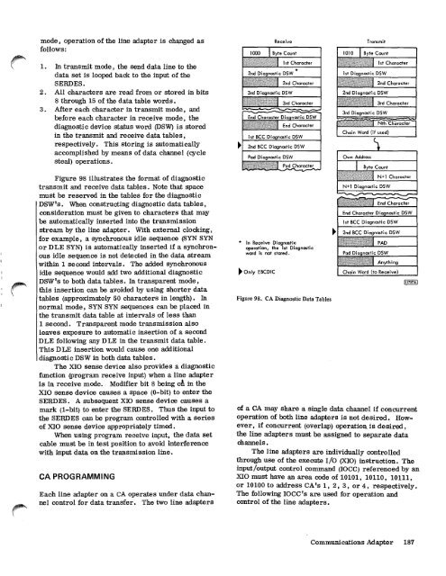
mode, operation of <strong>the</strong> line adapter is changed asfollows:1. In transmit mode, <strong>the</strong> send data line to <strong>the</strong>data set is looped back to <strong>the</strong> input of <strong>the</strong>SERDES.2. <strong>All</strong> characters are read from or stored in bits8 through 15 of <strong>the</strong> data table words.3. After each character in transmit mode, andbefore each character in receive mode, <strong>the</strong>diagnostic device status word (DSW) is storedin <strong>the</strong> transmit and receive data tables,respectively. This storing is automaticallyaccomplished by means of data channel (cyclesteal) operations.Figure 98 illustrates <strong>the</strong> format of diagnostictransmit and receive data tables. Note that spacemust be reserved in <strong>the</strong> tables for <strong>the</strong> diagnosticDSW's. When constructing diagnostic data tables,consideration must be given to characters that maybe automatically inserted into <strong>the</strong> transmissionstream by <strong>the</strong> line adapter. With external clocking,for example, a synchronous idle sequence (SYN SYNor DLE SYN) is automatically inserted if a synchronousidle sequence is not detected in <strong>the</strong> data streamwithin 1 second intervals. The added synchronousidle sequence would add two additional diagnosticDSW's to both data tables. In transparent mode,this insertion can be avoided by using shorter datatables (approximately 50 characters in length). Innormal mode, SYN SYN sequences can be placed in<strong>the</strong> transmit data table at intervals of less than1 second. Transparent mode transmission alsoleaves exposure to automatic insertion of a secondDLE following any DLE in <strong>the</strong> transmit data table.This DLE insertion would cause one additionaldiagnostic DSW in both data tables.The XIO sense device also provides a diagnosticfunction (program receive input) when a line adapteris in receive mode. Modifier bit 8 being di in <strong>the</strong>XIO sense device causes a space (0-bit) to enter <strong>the</strong>SERDES. A subsequent XIO sense device causes amark (1-bit) to enter <strong>the</strong> SERDES. Thus <strong>the</strong> input to<strong>the</strong> SERDES can be program controlled with a seriesof XIO sense device appropriately timed.When using program receive input, <strong>the</strong> data setcable must be in test position to avoid interferencewith input data on <strong>the</strong> transmission line.CA PROGRAMMINGEach line adapter on a CA operates under data channelcontrol for data transfer. The two line adaptersReceive1000 I Byte Count2,d Di,gnostic DSW3rd Di agnostic DSW1st Character2nd Character3rd CharacterEnd Character Diagnostic DSWEnd Character1st BCC Diagnostic DSW2nd BCC Diagnostic DSWPad Diagnostic DSWPad Character* In Receive Diagnosticoperation, <strong>the</strong> 1st Diagnosticword is not stored.Only EBCDICFigure 98. CA Diagnostic Data TablesOwn AddressITransmit1010 I Byte Count1s t Dicdd tic DSW2nd DI,or,c6tic DSWByte CountN+1 CharacterN+1 Diagnostic DSW---,..--,.....--,---,...---..........End CharacterEnd Character Diagnostic DSW1st BCC Diagnostic DSW2nd BCC Diagnostic DSWPADPod D n i c tic DSW1st Character2nd Character3rd Character3rd Dicdn,tic DSWChain Word (if used)Nth CharacterAnythingChain Word (to Receive)111737Aof a CA may share a single data channel if concurrentoperation of both line adapters is not desired. However,if concurrent (overlap) operation, is desired,<strong>the</strong> line adapters must be assigned to separate datachannels.The line adapters are individually controlledthrough use of <strong>the</strong> execute I/O (XIO) instruction. Theinput/output control command (IOCC) referenced by anXIO must have an area code of 10101, 10110, 10111,or 10100 to address CA's 1, 2, 3, or 4, respectively.The following IOCC's are used for operation andcontrol of <strong>the</strong> line adapters.Communications Adapter 187


