

Systems Reference Library - All about the IBM 1130 Computing ...
Systems Reference Library - All about the IBM 1130 Computing ...
Systems Reference Library - All about the IBM 1130 Computing ...
- No tags were found...

Create successful ePaper yourself
Turn your PDF publications into a flip-book with our unique Google optimized e-Paper software.
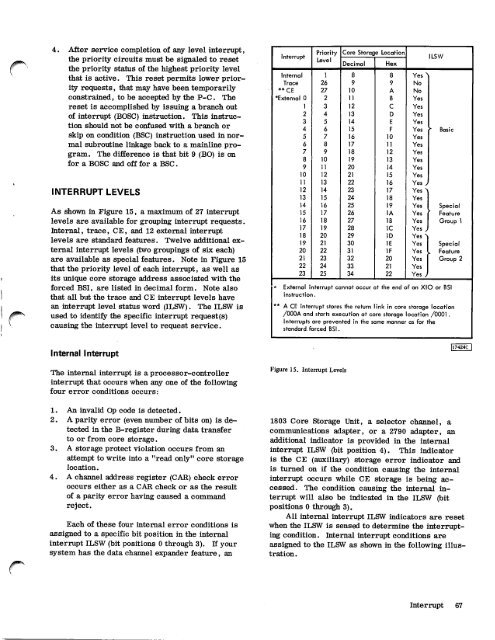
4. After service completion of any level interrupt,<strong>the</strong> priority circuits must be signaled to reset<strong>the</strong> priority status of <strong>the</strong> highest priority levelthat is active. This reset permits lower priorityrequests, that may have been temporarilyconstrained, to be accepted by <strong>the</strong> P-C. Thereset is accomplished by issuing a branch outof interrupt (BOSC) instruction. This instructionshould not be confused with a branch orskip on condition (BSC) instruction used in normalsubroutine linkage back to a mainline program.The difference is that bit 9 (BO) is onfor a BOSC and off for a BSC.INTERRUPT LEVELSAs shown in Figure 15, a maximum of 27 interruptlevels are available for grouping interrupt requests.Internal, trace, CE, and 12 external interruptlevels are standard features. Twelve additional externalinterrupt levels (two groupings of six each)are available as special features. Note in Figure 15that <strong>the</strong> priority level of each interrupt, as well asits unique core storage address associated with <strong>the</strong>forced BSI, are listed in decimal form. Note alsothat all but <strong>the</strong> trace and CE interrupt levels havean interrupt level status word (ILSW). The ILSW isused to identify <strong>the</strong> specific interrupt request(s)causing <strong>the</strong> interrupt level to request service.Ipt nterruPriorityLevelCore Storage LocationDecimalHexILSWInternal 1 8 8 YesTrace 26 9 9 No" CE 27 10 A No*External 0 2 11 B Yes1 3 12 C Yes2 4 13 D Yes3 5 14 E Yes4 6 15 F Yes Basic5 7 16 10 Yes6 8 17 11 Yes7 9 18 12 Yes8 10 19 13 Yes9 11 20 14 Yes10 12 21 15 Yes11 13 22 16 Yes12 14 23 17 Yes13 15 24 18 Yes14 16 25 19 Yes Special15 17 26 lA Yes Feature16 18 27 1B Yes Group 117 19 28 IC Yes18 20 29 ID Yes19 21 30 1E Yes Special20 22 31 1F Yes Feature21 23 32 20 Yes Group 222 24 33 21 Yes23 25 34 22 Yes* External interrupt cannot occur at <strong>the</strong> end of an X10 or BSIinstruction.** A CE interrupt stores <strong>the</strong> return link in core storage location/000A and starts execution at core storage location /0001.Interrupts are prevented in <strong>the</strong> same manner as for <strong>the</strong>standard. forced BSI.Internal InterruptThe internal interrupt is a processor-controllerinterrupt that occurs when any one of <strong>the</strong> followingfour error conditions occurs:1. An invalid Op code is detected.2. A parity error (even number of bits on) is detectedin <strong>the</strong> B-register during data transferto or from core storage.3. A storage protect violation occurs from anattempt to write into a "read only" core storagelocation.4. A channel address register (CAR) check erroroccurs ei<strong>the</strong>r as a CAR check or as <strong>the</strong> resultof a parity error having caused a commandreject.Each of <strong>the</strong>se four internal error conditions isassigned to a specific bit position in <strong>the</strong> internalinterrupt ILSW (bit positions 0 through 3). If yoursystem has <strong>the</strong> data channel expander feature, anFigure 15. Interrupt Levels117424C1803 Core Storage Unit, a selector channel, acommunications adapter, or a 2790 adapter, anadditional indicator is provided in <strong>the</strong> internalinterrupt ILSW (bit position 4). This indicatoris <strong>the</strong> CE (auxiliary) storage error indicator andis turned on if <strong>the</strong> condition causing <strong>the</strong> internalinterrupt occurs while CE storage is being accessed.The condition causing <strong>the</strong> internal interruptwill also be indicated in <strong>the</strong> ILSW (bitpositions 0 through 3).<strong>All</strong> internal interrupt ILSW indicators are resetwhen <strong>the</strong> ILSW is sensed to determine <strong>the</strong> interruptingcondition. Internal interrupt conditions areassigned to <strong>the</strong> ILSW as shown in <strong>the</strong> following illustration.Interrupt 67


