Dell Power Solutions
Dell Power Solutions
Dell Power Solutions
- No tags were found...

Create successful ePaper yourself
Turn your PDF publications into a flip-book with our unique Google optimized e-Paper software.
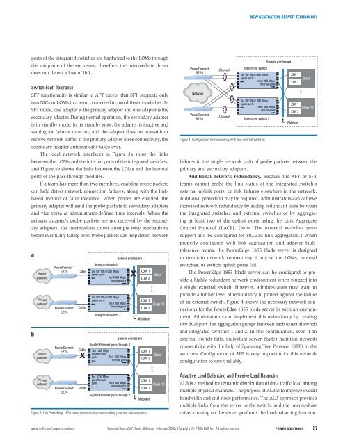
NEW-GENERATION SERVER TECHNOLOGYports of the integrated switches are hardwired to the LOMs throughthe midplane of the enclosure; therefore, the intermediate driverdoes not detect a loss of link.Switch Fault ToleranceSFT functionality is similar to AFT except that SFT supports onlytwo NICs or LOMs in a team connected to two different switches. InSFT mode, one adapter is the primary adapter and one adapter is thesecondary adapter. During normal operation, the secondary adapteris in standby mode. In its standby state, the adapter is inactive andwaiting for failover to occur, and the adapter does not transmit orreceive network traffic. If the primary adapter loses connectivity, thesecondary adapter automatically takes over.The local network interfaces in Figure 3a show the linksbetween the LOMs and the internal ports of the integrated switches,and Figure 3b shows the links between the LOMs and the internalports of the pass-through modules.If a team has more than two members, enabling probe packetscan help detect network connection failures, along with the linkbasedmethod of fault tolerance. When probes are enabled, theprimary adapter will send the probe packets to secondary adaptersand vice versa at administrator-defined time intervals. When theprimary adapter’s probe packets are not received by the secondaryadapters, the intermediate driver attempts retry mechanismsbefore eventually failing over. Probe packets can help detect networkabPublicnetworkPrivatenetworkPublicnetworkPrivatenetwork<strong>Power</strong>Connect 5224<strong>Power</strong>Connect5224<strong>Power</strong>Connect5224<strong>Power</strong>Connect5224CableCableCableCableIntegrated switch 1Six 10/100/1000 Mbpsuplink portsTen 1000 Mbpsinternal portsSix 10/100/1000 Mbpsuplink portsTen 1000 Mbpsinternal portsIntegrated switch 2Server enclosureGigabit Ethernet pass-through 1Ten 1000 Mbpspass-throughports Ten 1000 Mbpsinternal portsTen1000 Mbpspass-throughports Ten1000 Mbpsinternal portsServer enclosureGigabit Ethernet pass-through 2Figure 3. <strong>Dell</strong> <strong>Power</strong>Edge 1855 blade server architecture showing potential failover pointsLOM 1LOM 2LOM 1LOM 2MidplaneLOM 1LOM 2LOM 1LOM 2MidplaneBlade 1Blade 10Blade 1Blade 10<strong>Power</strong>Connect5224Network<strong>Power</strong>Connect5224ChannelsChannelsFigure 4. Configuration for redundancy with two external switchesfailures in the single network path of probe packets between theprimary and secondary adapters.Additional network redundancy. Because the AFT or SFTteams cannot probe the link status of the integrated switch’sexternal uplink ports, or link failures elsewhere in the network,additional protection may be required. Administrators can achieveincreased network redundancy by adding redundant links betweenthe integrated switches and external switches or by aggregatingat least two of the uplink ports using the Link AggregateControl Protocol (LACP). (Note: The external switches mustsupport and be configured for 802.3ad link aggregation.) Whenproperly configured with link aggregation and adapter faulttoleranceteams, the <strong>Power</strong>Edge 1855 blade server is designedto maintain network connectivity if any of the LOMs, internalswitches, or switch uplink ports fail.The <strong>Power</strong>Edge 1855 blade server can be configured to providea highly redundant network environment when plugged intoa single external switch. However, administrators may want toprovide a further level of redundancy to protect against the failureof an external switch. Figure 4 shows the necessary network connectionsfor the <strong>Power</strong>Edge 1855 blade server in such an environment.Administrators can implement this redundancy by creatingtwo dual-port link aggregation groups between each external switchand integrated switches 1 and 2. In this configuration, even if anexternal switch fails, individual server blades maintain networkconnectivity with the help of Spanning Tree Protocol (STP) in theswitches. Configuration of STP is very important for this networkconfiguration to work reliably.Server enclosureIntegrated switch 1Six 10/100/1000 MbpsLOM 1uplink portsTen 1000 Mbps LOM 2internal portsSix 10/100/1000 Mbpsuplink portsTen 1000 Mbpsinternal portsIntegrated switch 2Adaptive Load Balancing and Receive Load BalancingLOM 1LOM 2MidplaneBlade 1Blade 10ALB is a method for dynamic distribution of data traffic load amongmultiple physical channels. The purpose of ALB is to improve overallbandwidth and end-node performance. The ALB approach providesmultiple links from the server to the switch, and the intermediatedriver running on the server performs the load-balancing function.www.dell.com/powersolutions Reprinted from <strong>Dell</strong> <strong>Power</strong> <strong>Solutions</strong>, February 2005. Copyright © 2005 <strong>Dell</strong> Inc. All rights reserved. POWER SOLUTIONS 27