9.5.1 Operation (2)Factory settingThe setpoint is a value suitable for the <strong>Hydro</strong> <strong>MPC</strong> boostersystem in question. The factory setting may have been changedin the start-up menu.9.5.2 System operating mode (2.1.1)ABCFig. 17OperationDescriptionThe column shows the setting range. In closed-loop control, itcorresponds to the range of the primary sensor, here 0-145 psi. Inopen-loop control, the setting range is 0-100 %.At the left hand of the column, the selected setpoint 1 (A) isshown, i.e. the value set in the display. At the right hand of thecolumn, the current setpoint (B) is shown, i.e. the setpoint actingas reference for the PI controller. If no kind of external setpointinfluence has been selected, the two values will be identical. Thecurrent measured value (discharge pressure) is shown as thegrey part of the column (C). See sections 9.7.5 External setpointinfluence (4.1.3) and 9.7.6 Setting of influence function (4.1.3.2).Below the display is a menu line for setting of setpoint 1 andselection of operating mode, including the operating modesNormal and Stop. It is possible to select further settings: systemoperating mode, control mode, setpoints for closed and open loopas well as individual pump control.Setting rangeSetpoint:Closed-loop control: Measuring range of the primary sensorOpen-loop control: 0-100 %Setting via control panelSetpoint:1. Mark the Operation menu with .2. Mark Setpoint 1 with or . Set the value with or.3. Save with .Operating mode:1. Mark the Operation menu with .2. Mark operating mode Normal or Stop with or . Savewith .Further settings:1. Mark the Operation menu with .2. Mark Further settings with or , and press .3. Select one of the settings below with or , and press:• system operating mode (see section 9.5.2)• control mode (see section 9.5.3)• setpoints (see section 9.5.4)• individual pump control (see section 9.5.6).TM04 6196 5009Fig. 18System operating modeDescription<strong>Hydro</strong> <strong>MPC</strong> can be set to six different operating modes. Normal isthe typical setting. See section 9.4.3 Operating mode (1.2.1).The performance of the operating modes Max., Min., Userdefinedand Emergency run can be set in the Settings menu.In the display shown, it is poss ble to go directly to the Settingsmenu in order to set the pump performance or the setpoint.Setting rangeIt is possible to select the operating modes Normal, Max., Min.,User-defined, Stop and Emergency run.Setting via control panel1. Mark the Operation menu with .2. Mark Further settings with or , and press .3. Mark System operating mode with or , and press.4. Select the desired operating mode by marking one of the lineswith check boxes with or , and press .5. In order to set the performance in min., max., user-definedduty or emergency run, mark the desired line at the bottom ofthe display, and press .See sections 9.7.33 Min., max. and user-defined duty (4.3.14)and 9.7.25 Emergency run (4.3.5).Factory settingNormal.TM03 8951 480724
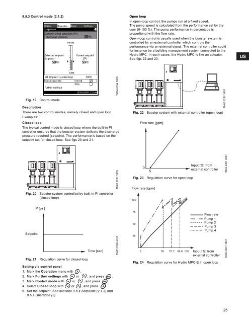
9.5.3 Control mode (2.1.2)Open loopIn open-loop control, the pumps run at a fixed speed.The pump speed is calculated from the performance set by theuser (0-100 %). The pump performance in percentage isproportional with the flow rate.Open-loop control is usually used when the booster system iscontrolled by an external controller which controls theperformance via an external signal. The external controller couldfor instance be a building management system connected to the<strong>Hydro</strong> <strong>MPC</strong>. In such cases, the <strong>Hydro</strong> <strong>MPC</strong> is like an actuator.See figs 22 and 23.Fig. 19Control modeDescriptionThere are two control modes, namely closed and open loop.Examples:Closed loopThe typical control mode is closed loop where the built-in PIcontroller ensures that the booster system delivers the dischargepressure required (setpoint). The performance is based on thesetpoint set for closed loop. See figs 20 and 21.TM04 6194 5009Fig. 22 Booster system with external controller (open loop)Flow rate [gpm]TM03 2232 3905TM03 2231 3905Fig. 2305Flow rate [gpm]Regulation curve for open loopInput [%] fromexternal controllerTM03 2391 3607Fig. 20Booster system controlled by built-in PI controller(closed loop)100SetpointFig. 21P [ps ]Regulation curve for closed loopTime [sec]Setting via control panel1. Mark the Operation menu with .2. Mark Further settings with or , and press .3. Mark Control mode with or , and press .4. Select Closed loop with or , and press .5. Set the setpoint. See sections 9.5.4 Setpoints (2.1.3) and9.5.1 Operation (2).TM03 2390 41057550255Fig. 2450 70.786.6 100Flow ratePump 1Pump 2Pump 3Pump 4Input [%] fromexternal controllerRegulation curve for <strong>Hydro</strong> <strong>MPC</strong>-E in open loopTM03 9977 480725