


You also want an ePaper? Increase the reach of your titles
YUMPU automatically turns print PDFs into web optimized ePapers that Google loves.
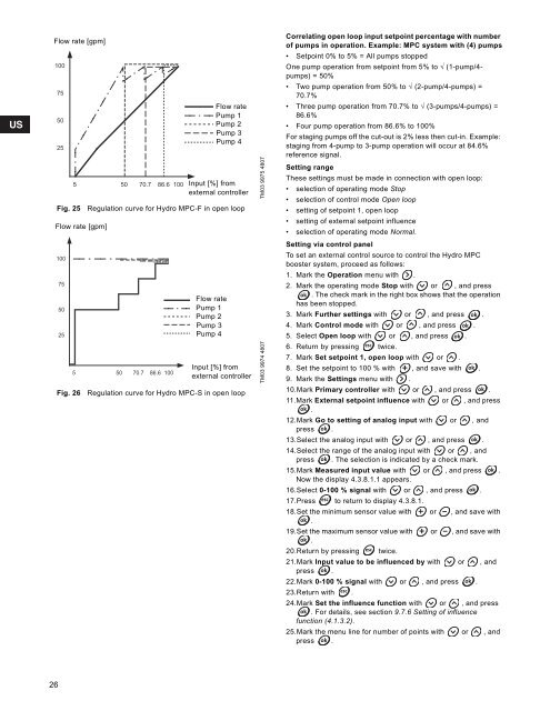
Flow rate [gpm]1007550255Fig. 25Flow rate [gpm]1007550255Fig. 2650 70.7Flow ratePump 1Pump 2Pump 3Pump 486.6 100 Input [%] fromexternal controllerRegulation curve for <strong>Hydro</strong> <strong>MPC</strong>-F in open loop50 70.786.6 100Flow ratePump 1Pump 2Pump 3Pump 4Input [%] fromexternal controllerRegulation curve for <strong>Hydro</strong> <strong>MPC</strong>-S in open loopTM03 9975 4807TM03 9974 4807Correlating open loop input setpoint percentage with numberof pumps in operation. Example: <strong>MPC</strong> system with (4) pumps• Setpoint 0% to 5% = All pumps stoppedOne pump operation from setpoint from 5% to √ (1-pump/4-pumps) = 50%• Two pump operation from 50% to √ (2-pump/4-pumps) =70.7%• Three pump operation from 70.7% to √ (3-pumps/4-pumps) =86.6%• Four pump operation from 86.6% to 100%For staging pumps off the cut-out is 2% less then cut-in. Example:staging from 4-pump to 3-pump operation will occur at 84.6%reference signal.Setting rangeThese settings must be made in connection with open loop:• selection of operating mode Stop• selection of control mode Open loop• setting of setpoint 1, open loop• setting of external setpoint influence• selection of operating mode Normal.Setting via control panelTo set an external control source to control the <strong>Hydro</strong> <strong>MPC</strong>booster system, proceed as follows:1. Mark the Operation menu with .2. Mark the operating mode Stop with or , and press. The check mark in the right box shows that the operationhas been stopped.3. Mark Further settings with or , and press .4. Mark Control mode with or , and press .5. Select Open loop with or , and press .6. Return by pressing twice.7. Mark Set setpoint 1, open loop with or .8. Set the setpoint to 100 % with , and save with .9. Mark the Settings menu with .10.Mark Primary controller with or , and press .11.Mark External setpoint influence with or , and press.12.Mark Go to setting of analog input with or , andpress .13.Select the analog input with or , and press .14.Select the range of the analog input with or , andpress . The selection is indicated by a check mark.15.Mark Measured input value with or , and press .Now the display 4.3.8.1.1 appears.16.Select 0-100 % signal with or , and press .17.Press to return to display 4.3.8.1.18.Set the minimum sensor value with or , and save with.19.Set the maximum sensor value with or , and save with.20.Return by pressing twice.21.Mark Input value to be influenced by with or , andpress .22.Mark 0-100 % signal with or , and press .23.Return with .24.Mark Set the influence function with or , and press. For details, see section 9.7.6 Setting of influencefunction (4.1.3.2).25.Mark the menu line for number of points with or , andpress .26


