You also want an ePaper? Increase the reach of your titles
YUMPU automatically turns print PDFs into web optimized ePapers that Google loves.
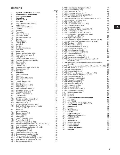
CONTENTSPage1. Symbols used in this document 62. Scope of these instructions 63. Product description 64. Nameplate 75. Software label 76. Type key 86.1 Examples of control variants 97. Installation 117.1 Mechanical installation 117.1.1 Location 117.1.2 Pipework 117.1.3 Foundation 117.1.4 Vibration dampers 117.1.5 Expansion joints 117.2 Electrical installation 127.3 Start-up 128. Control panel 148.1 Display (pos. 1) 148.1.1 Menu line 148.1.2 Top line 148.1.3 Graphical illustration 148.1.4 Scroll bar 148.1.5 Bottom line 148.2 Buttons and indicator lights 158.2.1 Arrow to the right (pos. 2) 158.2.2 Help (pos. 3) 158.2.3 Up and down (pos. 4 and 5) 158.2.4 Plus and minus (pos. 6 and 7) 158.2.5 Esc (pos. 8) 158.2.6 Home (pos. 9) 158.2.7 Ok (pos. 10) 158.2.8 Indicator lights (pos. 11 and 12) 158.2.9 Contrast (pos. 13) 158.2.10 Back light 159. Functions 169.1 Tree of functions 169.2 Overview 199.3 Description of functions 219.4 Status (1) 219.4.1 Current alarms (3.1) 219.4.2 System (1.2) 219.4.3 Operating mode (1.2.1) 229.4.4 Setpoint (1.2.2) 229.4.5 Setpoint influence (1.2.3) 229.4.6 Measured values (1.2.4) 239.4.7 Analog inputs (1.2.5) 239.4.8 Pump 1...6 (1.3 to 1.8) 239.5 Operation (2) 239.5.1 Operation (2) 249.5.2 System operating mode (2.1.1) 249.5.3 Control mode (2.1.2) 259.5.4 Setpoints (2.1.3) 279.5.5 Individual pump control (2.1.4) 279.5.6 Setting of individual operating mode(2.1.4.1 to 2.1.4.6) 289.6 Alarm (3) 299.6.1 Alarm status (3) 299.6.2 Current alarms (3.1) 349.6.3 Alarm log (3.2) 349.7 Settings (4) 349.7.1 Primary controller (4.1) 359.7.2 PI controller (4.1.1) 359.7.3 Alternative setpoints (4.1.2) 359.7.4 Alternative setpoints 2 to 7 (4.1.2.1 to 4.1.2.7) 369.7.5 External setpoint influence (4.1.3) 369.7.6 Setting of influence function (4.1.3.2) 379.7.7 Primary sensor (4.1.4) 379.7.8 Clock program (4.1.6) 389.7.9 Proportional pressure (4.1.7) 389.7.10 S-system configuration (4.1.8) 399.7.11 Pump cascade control (4.2) 399.7.12 Min. time between start/stop (4.2.1) 409.7.13 Max. number of starts/hour (4.2.1) 409.7.14 Standby pumps (4.2.3) 419.7.15 Forced pump changeover (4.2.4) 419.7.16 Pump test run (4.2.5) 419.7.17 Pilot pump (4.2.6) 429.7.18 Pump stop attempt (4.2.7) 429.7.19 Pump start and stop speed (4.2.8) 439.7.20 Min. performance (4.2.9) 439.7.21 Compensation for pump start-up time (4.2.10) 449.7.22 Secondary functions (4.3) 449.7.23 Stop function (4.3.1) 449.7.24 Soft pressure build-up (4.3.3) 469.7.25 Emergency run (4.3.5) 479.7.26 Digital inputs (4.3.7) 489.7.27 Functions of digital inputs (4.3.7.1) 489.7.28 Analog inputs (4.3.8) 499.7.29 Analog inputs (4.3.8.1 to 4.3.8.7) 499.7.30 Analog inputs and measured value(4.3.8.1.1 to 4.3.8.7.1) 509.7.31 Digital outputs (4.3.9) 509.7.32 Functions of digital outputs (4.3.9.1 to 4.3.9.16) 519.7.33 Min., max. and user-defined duty (4.3.14) 519.7.34 Min. duty (4.3.14.1) 519.7.35 Max. duty (4.3.14.2) 529.7.36 User-defined duty (4.3.14.3) 529.7.37 Pump curve data (4.3.19) 539.7.38 Control source (4.3.20) 549.7.39 Fixed inlet pressure (4.3.22) 549.7.40 Flow estimation (4.3.23) 549.7.41 Monitoring functions (4.4) 559.7.42 Dry-running protection (4.4.1) 559.7.43 Dry-running protection with pressure/levelswitch (4.4.1.1) 569.7.44 Dry-running protection with pressure transmitter(4.4.1.2) 569.7.45 Dry-running protection with level transmitter (4.4.1.3) 579.7.46 Min. pressure (4.4.2) 579.7.47 Max. pressure (4.4.3) 589.7.48 External fault (4.4.4) 589.7.49 Limit 1 and 2 exceeded (4.4.5 and 4.4.6) 599.7.50 Pumps outside duty range (4.4.7) 599.7.51 Pressure relief (4.4.8) 609.7.52 Functions, CU 351 (4.5) 619.7.53 Display language (4.5.1) 619.7.54 Display units (4.5.2) 619.7.55 Date and time (4.5.3) 629.7.56 Passwords (4.5.4) 639.7.57 Ethernet (4.5.5) 639.7.58 GENIbus number (4.5.6) 639.7.59 Software status (4.5.9) 649.8 Data communication 659.8.1 Ethernet 659.8.2 GENIbus 6710. External variable frequency drive 6810.1 VLT 2800 6810.2 VLT FC 202 6910.3 Configuration of E-pump(s), if any 7011. Fault finding chart 7112. Maintenance 7212.1 Pumps 7212.2 Motor bearings 7212.3 CU 351 7213. Frost protection 7214. Taking out of operation 7215. Technical data 7215.1 Pressure 7215.2 Temperature 7315.3 Relative humidity 7315.4 Sound pressure 7316. Electrical data 7317. Related documents 7318. Disposal 735


