


You also want an ePaper? Increase the reach of your titles
YUMPU automatically turns print PDFs into web optimized ePapers that Google loves.
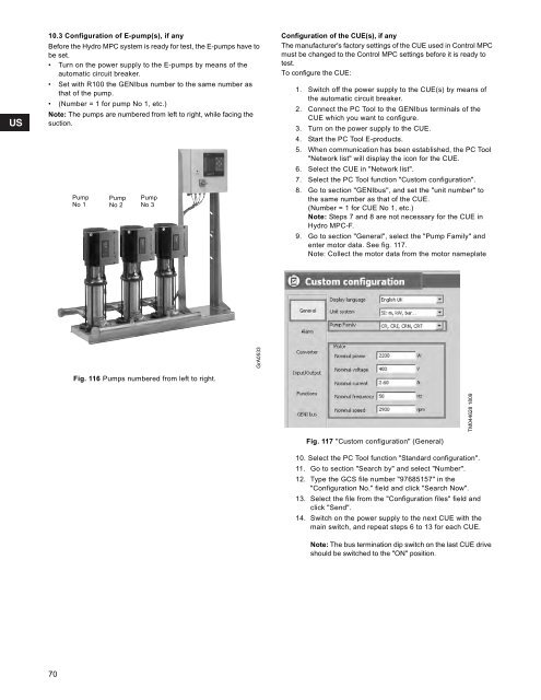
10.3 Configuration of E-pump(s), if anyBefore the <strong>Hydro</strong> <strong>MPC</strong> system is ready for test, the E-pumps have tobe set.• Turn on the power supply to the E-pumps by means of theautomatic circuit breaker.• Set with R100 the GENIbus number to the same number asthat of the pump.• (Number = 1 for pump No 1, etc.)Note: The pumps are numbered from left to right, while facing thesuction.PumpNo 1PumpNo 2PumpNo 3Configuration of the CUE(s), if anyThe manufacturer's factory settings of the CUE used in Control <strong>MPC</strong>must be changed to the Control <strong>MPC</strong> settings before it is ready totest.To configure the CUE:1. Switch off the power supply to the CUE(s) by means ofthe automatic circuit breaker.2. Connect the PC Tool to the GENIbus terminals of theCUE which you want to configure.3. Turn on the power supply to the CUE.4. Start the PC Tool E-products.5. When communication has been established, the PC Tool"Network list" will display the icon for the CUE.6. Select the CUE in "Network list".7. Select the PC Tool function "Custom configuration".8. Go to section "GENIbus", and set the "unit number" tothe same number as that of the CUE.(Number = 1 for CUE No 1, etc.)Note: Steps 7 and 8 are not necessary for the CUE in<strong>Hydro</strong> <strong>MPC</strong>-F.9. Go to section "General", select the "Pump Family" andenter motor data. See fig. 117.Note: Collect the motor data from the motor nameplateGrA0533Fig. 116 Pumps numbered from left to right.TM044628 1809Fig. 117 "Custom configuration" (General)10. Select the PC Tool function "Standard configuration".11. Go to section "Search by" and select "Number".12. Type the GCS file number "97685157" in the"Configuration No." field and click "Search Now".13. Select the file from the "Configuration files" field andclick "Send".14. Switch on the power supply to the next CUE with themain switch, and repeat steps 6 to 13 for each CUE.Note: The bus termination dip switch on the last CUE driveshould be switched to the "ON" position.70


