- Page 1 and 2:
GPS PLOTTER/SOUNDERModelGP-1670F/GP
- Page 3 and 4:
IMPORTANT NOTICESGeneral• This ma
- Page 5 and 6:
SAFETY INSTRUCTIONSCAUTIONDo no tur
- Page 7 and 8:
TABLE OF CONTENTS3.2.3 How to enter
- Page 9 and 10:
TABLE OF CONTENTS9. MEMORY CARD OPE
- Page 11 and 12:
FOREWORDA Word to GP-1670F, GP-1870
- Page 13 and 14:
SYSTEM CONFIGURATIONThe environment
- Page 15 and 16:
EQUIPMENT LISTSName Type Code no. R
- Page 17 and 18:
1. OPERATIONAL OVERVIEW1.1 Controls
- Page 19 and 20:
1. OPERATIONAL OVERVIEWTested SD ca
- Page 21 and 22:
1. OPERATIONAL OVERVIEW1.2 RotoKey
- Page 23 and 24:
1. OPERATIONAL OVERVIEW2D plotter d
- Page 25 and 26:
1. OPERATIONAL OVERVIEW1.6 The Curs
- Page 27 and 28:
1.8 Home Screen (Display Selection)
- Page 29 and 30:
1. OPERATIONAL OVERVIEW5. Select a
- Page 31 and 32:
1. OPERATIONAL OVERVIEWWind meter+n
- Page 33 and 34:
1. OPERATIONAL OVERVIEWHow to selec
- Page 35 and 36:
1. OPERATIONAL OVERVIEWAuto course-
- Page 37 and 38:
1. OPERATIONAL OVERVIEW4) Press the
- Page 39 and 40:
1. OPERATIONAL OVERVIEWItem Context
- Page 41 and 42:
1. OPERATIONAL OVERVIEW1.17 Tide In
- Page 43 and 44:
2. TRACKYour boat’s track is plot
- Page 45 and 46:
2.7 How to Delete Track by Color2.
- Page 47 and 48:
3. POINTS3.1 What is a Point?In nav
- Page 49 and 50:
3. POINTS[Hide]: Hide the icon and
- Page 51 and 52:
3. POINTS3.5 How to Select Visibili
- Page 53 and 54:
4. ROUTES4.1 What is a Route?Often
- Page 55 and 56:
4. ROUTES5) After you have entered
- Page 57 and 58:
4. ROUTES4. Select [EASY ROUTING] f
- Page 59 and 60:
4. ROUTES4.4 How to Insert a Point
- Page 61 and 62:
4. ROUTES4.7.2 Functions available
- Page 63 and 64:
4. ROUTES4.9 How to Display a Route
- Page 65 and 66:
5. NAVIGATIONThis chapter shows you
- Page 67 and 68:
5. NAVIGATION• A red line runs be
- Page 69 and 70:
6. MAP SETTINGS, 2D PERSPEC-TIVE/3D
- Page 71 and 72:
6. MAP SETTINGS, 2D PERSPECTIVE/3D
- Page 73 and 74:
6. MAP SETTINGS, 2D PERSPECTIVE/3D
- Page 75 and 76:
6. MAP SETTINGS, 2D PERSPECTIVE/3D
- Page 77 and 78:
7. FISH FINDER OPERATIONS7.1 How th
- Page 79 and 80:
7.3 How to Activate the Fish Finder
- Page 81 and 82:
7. FISH FINDER OPERATIONSMarker zoo
- Page 83 and 84:
7. FISH FINDER OPERATIONS• The 60
- Page 85 and 86:
7.6 Manual Fish Finder Operation7.
- Page 87 and 88:
7. FISH FINDER OPERATIONSClutter7.7
- Page 89 and 90:
7. FISH FINDER OPERATIONS7.10 How t
- Page 91 and 92:
7.14.1 How to set an alarm7. FISH F
- Page 93 and 94:
7. FISH FINDER OPERATIONS7.15.2 How
- Page 95 and 96:
7.17 FISH FINDER Menu7. FISH FINDER
- Page 97 and 98:
7. FISH FINDER OPERATIONSItem[50 kH
- Page 99 and 100:
7. FISH FINDER OPERATIONSBottom con
- Page 101 and 102: 7. FISH FINDER OPERATIONSPlanktonA
- Page 103 and 104: 8. ALARMSThe plotter section has 11
- Page 105 and 106: 8. ALARMS8.4 XTE AlarmThe XTE (cros
- Page 107 and 108: 8. ALARMS8.8 Anchor AlarmThe anchor
- Page 109 and 110: 9. MEMORY CARD OPERATIONSThis syste
- Page 111 and 112: 9.6 How to Delete Files from an SD
- Page 113 and 114: 9. MEMORY CARD OPERATIONS9.8.3 How
- Page 115 and 116: 10. OTHER FUNCTIONS10.1 AIS Operati
- Page 117 and 118: 10.2 DSC Message Information10. OTH
- Page 119 and 120: 10. OTHER FUNCTIONS10.4 How to Sele
- Page 121 and 122: 10. OTHER FUNCTIONS10.5 Engine Disp
- Page 123 and 124: 11. CUSTOMIZING YOUR UNITThe defaul
- Page 125 and 126: 11. CUSTOMIZING YOUR UNIT11.3 SYSTE
- Page 127 and 128: 11. CUSTOMIZING YOUR UNIT[RESTART G
- Page 129 and 130: 12. MAINTENANCE,TROUBLESHOOTINGThis
- Page 131 and 132: 12. MAINTENANCE, TROUBLESHOOTINGPro
- Page 133 and 134: 12. MAINTENANCE, TROUBLESHOOTING12.
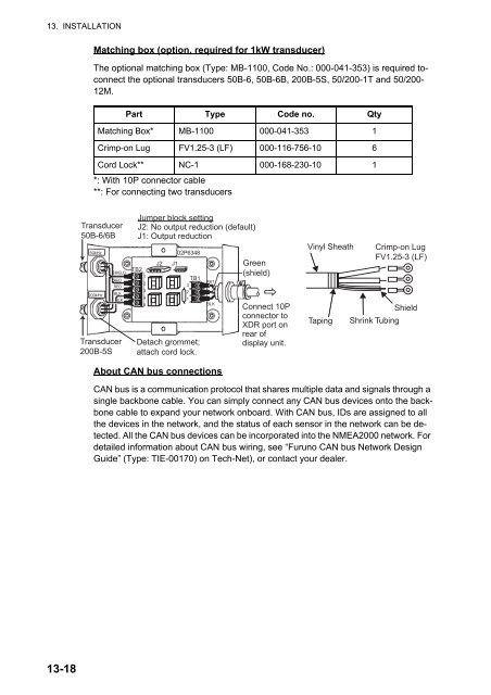
- Page 135 and 136: 13. INSTALLATION13.1 Installation o
- Page 137 and 138: 13. INSTALLATIONin a position where
- Page 139 and 140: 13.3.2 Transom mount transducer13.
- Page 141 and 142: 13. INSTALLATION3. Wipe off any san
- Page 143 and 144: 13. INSTALLATIONHow to install the
- Page 145 and 146: 13. INSTALLATIONHow to attach the s
- Page 147 and 148: 13. INSTALLATION8. Launch your boat
- Page 149 and 150: 13.5 Wiring13. INSTALLATIONAll wiri
- Page 151: 13. INSTALLATIONHow to extend cable
- Page 155 and 156: 13. INSTALLATION13.6.2 CAN bus inpu
- Page 157 and 158: 13. INSTALLATIONPGNDescription12748
- Page 159 and 160: APPENDIX 1 MENU TREEESC/MENU(long p
- Page 161 and 162: APPENDIX 1 MENU TREE11(Con’t from
- Page 163 and 164: APPENDIX 1 MENU TREE1(Con’t from
- Page 165 and 166: APPENDIX 2 ABBREVIATIONS, SYMBOLSAb
- Page 167 and 168: APPENDIX 2 ABBREVIATIONS, SYMBOLSSy
- Page 169 and 170: APPENDIX 3 JIS CABLE GUIDECables li
- Page 171 and 172: FURUNOGP-1670F/1870FSPECIFICATIONS
- Page 173 and 174: PACKING LIST GP-1670F-E 14CW-X-9852
- Page 175 and 176: D-1
- Page 177 and 178: D-3
- Page 179 and 180: D-5
- Page 181 and 182: INDEXNumerics2D perspective dispay.
- Page 183 and 184: INDEXrecording interval............
- Page 185: FURUNO Warranty for North AmericaFU