Liebert Challenger 3000 with iCOM
Liebert Challenger™ 3000 with iCOM Installation Manual - 3 ... - DCES
Liebert Challenger™ 3000 with iCOM Installation Manual - 3 ... - DCES
- No tags were found...

You also want an ePaper? Increase the reach of your titles
YUMPU automatically turns print PDFs into web optimized ePapers that Google loves.
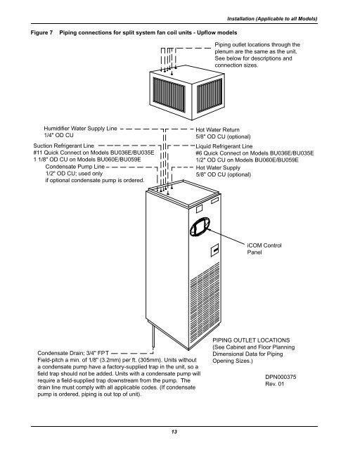
Installation (Applicable to all Models)Figure 7Piping connections for split system fan coil units - Upflow modelsPiping outlet locations through theplenum are the same as the unit.See below for descriptions andconnection sizes.Humidifier Water Supply Line1/4" OD CUSuction Refrigerant Line#11 Quick Connect on Models BU036E/BU035E1 1/8" OD CU on Models BU060E/BU059ECondensate Pump Line1/2" OD CU; used onlyif optional condensate pump is ordered.Hot Water Return5/8" OD CU (optional)Liquid Refrigerant Line#6 Quick Connect on Models BU036E/BU035E1/2" OD CU on Models BU060E/BU059EHot Water Supply5/8" OD CU (optional)<strong>iCOM</strong> ControlPanelCondensate Drain; 3/4" FPTField-pitch a min. of 1/8" (3.2mm) per ft. (305mm). Units <strong>with</strong>outa condensate pump have a factory-supplied trap in the unit, so afield trap should not be added. Units <strong>with</strong> a condensate pump willrequire a field-supplied trap downstream from the pump. Thedrain line must comply <strong>with</strong> all applicable codes. (If condensatepump is ordered, piping is out top of unit).PIPING OUTLET LOCATIONS(See Cabinet and Floor PlanningDimensional Data for PipingOpening Sizes.)DPN000375Rev. 0113