XV-15 litho - NASA's History Office
XV-15 litho - NASA's History Office
XV-15 litho - NASA's History Office

Create successful ePaper yourself
Turn your PDF publications into a flip-book with our unique Google optimized e-Paper software.
Figure 31.<br />
Bell 25-ft. diameter proprotor<br />
performance test in the Ames<br />
Research Center 40- by 80-ft.<br />
wind tunnel.<br />
(Ames Photograph<br />
AC70-5390)<br />
26<br />
For large-scale performance characteristics, the Bell<br />
25-foot diameter proprotor was tested in the Ames<br />
40- by 80-foot wind tunnel in November 1970 (figure<br />
31) as part of an earlier contracted effort. Ames also<br />
contracted with Bell and made arrangements with the<br />
Air Force Aero Propulsion Laboratory (AFAPL) for<br />
the March 1973 proprotor hover performance test at<br />
Wright-Patterson Air Force Base.<br />
While the fundamentals of tilt rotor aeromechanics<br />
were being explored, another group of researchers<br />
and engineers were investigating the flying qualities,<br />
crew station, and control law aspects of this class of<br />
VTOL aircraft. Model-scale wind tunnel tests, analytical<br />
modeling, and piloted simulations were used to<br />
address these issues.<br />
A series of tests was conducted with a 1/5- scale powered<br />
aeroelastic model of the Bell Model 300 tilt rotor<br />
aircraft design under an Ames contract. Hover tests<br />
conducted in September, October, and December of<br />
1972 with this model examined the performance and<br />
dynamic characteristics for operations near the ground.<br />
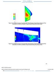
It was discovered that, in the helicopter mode, the downward flow from the rotors<br />
impinging on the ground produced a strong upward-moving flow below the aircraft’s<br />
longitudinal axis. This upwash, known as the “fountain,” impacts the lower<br />
surface of the fuselage with increasing strength as the aircraft descends to the<br />
ground. Because this fountain is somewhat unsteady, the major portion of this air<br />
mass is seen to skip from one side of the fuselage to the other (particularly on round<br />
cross-section fuselages), causing this fountain-flow to impinge, alternately, on the<br />
lower surface of the right or left wing. This condition can contribute to the lateral<br />
darting observed during the <strong>XV</strong>-3 flight tests and lead to a considerably high pilot<br />
workload during the landing operation. Also, the occurrence of the unsymmetrical<br />
aerodynamic loading on the wing surfaces produces a rolling moment that increases<br />
in magnitude, i.e. is statically destabilizing, as the aircraft descends toward the<br />
ground. 20 Recognition of these phenomena contributed to the development of<br />
improved stability augmentation control algorithms for future tilt rotor aircraft.<br />
Subsequent wind tunnel tests, conducted in the Vought Aeronautics low speed<br />
wind tunnel, Texas, from January through March 1973, documented the performance,<br />
static stability in yaw and pitch, and determined trimmed control positions<br />
in all flight configurations. These data were critical for the flight dynamics ana-<br />
20 R. L. Marr, K. W. Sambell, G. T. Neal, “Hover, Low Speed and Conversion Tests of a Tilt<br />
Rotor Aeroelastic Model.” V/STOL Tilt Rotor Study, vol. VI, Bell Helicopter Co., NASA<br />
CR-1146<strong>15</strong>, May 1973.