XV-15 litho - NASA's History Office
XV-15 litho - NASA's History Office
XV-15 litho - NASA's History Office

You also want an ePaper? Increase the reach of your titles
YUMPU automatically turns print PDFs into web optimized ePapers that Google loves.
44<br />
Test stand<br />
angle box<br />
Test stand<br />
low-speed<br />
gearbox<br />
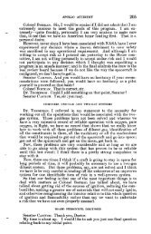
Figure 39.<br />
Bell test apparatus used for<br />
transmission qualification<br />
testing.<br />
Torque<br />
converter<br />
<strong>XV</strong>-<strong>15</strong><br />
Center gearbox<br />
<strong>XV</strong>-<strong>15</strong> Main<br />
transmission<br />
Extensive qualification test operations<br />
were then conducted on the Bell transmission<br />
test rig illustrated in figure 39.<br />
This apparatus placed the transmission<br />
elements in a continuous drive linkage<br />
that simulated the engine-input and the<br />
proprotor drive-output shafts flight<br />
loads. The test apparatus drive system<br />
was assembled so that a prescribed<br />
torque was applied to the <strong>XV</strong>-<strong>15</strong><br />
TRRA transmission which was then<br />
operated for a specified number of<br />
hours at a selected RPM. During these<br />
qualification tests a range of torque<br />
levels and RPM’s was applied to the<br />
left and right main transmissions, the<br />
engine coupling gearboxes, and the<br />
center gearbox.<br />
Over the next two years the qualification test program revealed problems that<br />
required modification of gear designs, gear and shaft welding processes, bearing<br />
designs, and lubrication and cooling arrangements.<br />
The transmission ground tests also included an evaluation and calibration of the output<br />
torque sensing system which was to provide the input to the torque indicator on<br />
the instrument panel. This sensing system consisted of concentric cylindrical shafts<br />
affixed to each other at one end. The inside shaft transmitted the torque while the<br />
outside shaft remained unloaded. The torque was measured by determining the magnitude<br />
of the deflection of the loaded (inside) shaft and comparing it to the undeflected,<br />
un-torqued (outside) shaft. This torque sensing device, however, did not provide<br />
output data of sufficient accuracy for a primary flight instrument. After considerable<br />
effort to correct the problem, Bell suggested a rather unusual approach. This was to<br />
make an exception to a standing <strong>XV</strong>-<strong>15</strong> TRRA Project <strong>Office</strong> and Bell policy and<br />
allow the use of research instrumentation system data for primary flight instrument<br />
data. The Project <strong>Office</strong> agreed and the transmission output torque indication in the<br />
cockpit was now to be obtained from research instrumentation strain gages mounted<br />
on the proprotor drive shaft (called the proprotor mast). The research instrumented<br />
proprotor mast had a calibration resolution of two to three percent, sufficient for the<br />
management of the aircraft. Despite concerns by Bell and Government engineers<br />
about the reliability and durability of this instrumentation-based torque indication<br />
system, it served the <strong>XV</strong>-<strong>15</strong> well during many years of flight operations.<br />
Fuel Cells<br />
Hydraulic drive<br />
Proprotor<br />
mast<br />
Test stand<br />
high-speed<br />
gearbox<br />
Torque<br />
converter<br />
During the formulation of the TRRA Program Plan, a prime focus of many<br />
discussions among members of the Government Project <strong>Office</strong> was the need