XV-15 litho - NASA's History Office
XV-15 litho - NASA's History Office
XV-15 litho - NASA's History Office

Create successful ePaper yourself
Turn your PDF publications into a flip-book with our unique Google optimized e-Paper software.
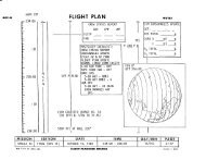
Figure 40.<br />
Proprotor response to<br />
cockpit control input.<br />
46<br />
Flight Controls<br />
One of the more difficult technical challenges in the development of the <strong>XV</strong>-<strong>15</strong><br />
TRRA was the design of the flight control system. The <strong>XV</strong>-3 had revealed various<br />
degrees of flying qualities, handling qualities, and pilot work load deficiencies<br />
in nearly all flight modes. It was the job of the engineers to address these<br />
problems and produce a flight control system that could meet existing and pending<br />
handling qualities and stability and control requirements from military and<br />
Federal Aviation Administration (FAA) standards. While normal operations<br />
would be conducted by a crew of two, the <strong>XV</strong>-<strong>15</strong> control system was designed to<br />
permit a single pilot to perform all normal and emergency procedures from either<br />
seat.<br />
The controls effort was divided into four categories: Primary Flight Controls,<br />
Secondary Flight Controls, Thrust/Power Management System, and Automatic<br />
Flight Controls.<br />
Because the tilt rotor aircraft combines the flight characteristics of a conventional<br />
helicopter and those of a fixed-wing airplane, its flight control system had to<br />
blend the basic elements of these two<br />
vehicle types. The flight deck of the<br />
TRRA was configured so that each<br />
pilot station had complete controls for<br />
pitch, roll, yaw, and thrust in all<br />
modes of flight. They consisted of<br />
control sticks, rudder pedals with<br />
brakes, and power levers (for proprotor<br />
collective pitch and engine throttle<br />
functions). A single set of airplanetype<br />
throttles, rpm governor, flap, and<br />
landing gear controls were located in<br />
the center console.<br />
Collective Lateral Cyclic<br />
Longitudinal Cyclic Directional<br />
In the helicopter mode, the controls<br />
apply collective or cyclic blade pitch<br />
changes to the rotors to produce control<br />
moments and forces. Fore and aft<br />
cyclic pitch (produced by moving the<br />
center control stick fore and aft) provides<br />
longitudinal control, and differential<br />
cyclic pitch (in response to rudder<br />
pedal motion) produces directional<br />
control. Collective pitch commanded<br />
by collective lever input is used for<br />
vertical control, and differential collective<br />
pitch, resulting from center stick