- Page 1 and 2:
McNary-John Day Transmission Line P
- Page 3 and 4:
ii Maintenance.....................
- Page 5 and 6:
List of Figures S-1 Vicinity Map ..
- Page 7 and 8:
3-17 Sensitive Wildlife Species Pot
- Page 9 and 10:
Summary problem of lack of power, p
- Page 11 and 12:
BPA McNary-John Day Transmission Pr
- Page 13 and 14:
Alternatives BPA McNary-John Day Tr
- Page 15 and 16:
BPA McNary-John Day Transmission Pr
- Page 17 and 18:
BPA McNary-John Day Transmission Pr
- Page 19 and 20:
Mitigation BPA McNary-John Day Tran
- Page 21 and 22:
BPA McNary-John Day Transmission Pr
- Page 23 and 24:
Environmental Consequences—Propos
- Page 25 and 26:
Vegetation Affected Environment BPA
- Page 27 and 28:
BPA McNary-John Day Transmission Pr
- Page 29 and 30:
Operation and Maintenance BPA McNar
- Page 31 and 32:
Cultural Resources Affected Environ
- Page 33 and 34:
BPA McNary-John Day Transmission Pr
- Page 35 and 36:
Socioeconomics, Public Services, an
- Page 37 and 38:
Transportation Affected Environment
- Page 39 and 40:
Environmental Consequences—Propos
- Page 41 and 42:
BPA McNary-John Day Transmission Pr
- Page 43 and 44:
BPA McNary-John Day Transmission Pr
- Page 45 and 46:
Table S-2: Summary of Impacts of Sh
- Page 47 and 48:
BPA McNary-John Day Transmission Pr
- Page 49 and 50:
Transmission Infrastructure BPA McN
- Page 51 and 52:
BPA McNary-John Day Transmission Pr
- Page 53 and 54:
Plymouth Generating Facility BPA Mc
- Page 55 and 56:
Chapter 2 Proposed Action and Alter
- Page 57 and 58:
2 2-2 Proposed Action and Alternati
- Page 59 and 60:
2 2-4 Proposed Action and Alternati
- Page 61 and 62:
2 2-6 Proposed Action and Alternati
- Page 63 and 64:
2 2-8 Proposed Action and Alternati
- Page 65 and 66:
2 2-10 Proposed Action and Alternat
- Page 67 and 68:
2 2-12 Proposed Action and Alternat
- Page 69 and 70:
2 2-14 Proposed Action and Alternat
- Page 71 and 72:
2 2-16 Proposed Action and Alternat
- Page 73 and 74:
2 2-18 Proposed Action and Alternat
- Page 76 and 77:
Table 2-3: Summary of Impacts and M
- Page 78 and 79:
Table 2-3: Summary of Impacts and M
- Page 80 and 81:
Table 2-3: Summary of Impacts and M
- Page 82 and 83:
Table 2-3: Summary of Impacts and M
- Page 84 and 85:
Chapter 3 Affected Environment, Env
- Page 86 and 87:
3 3-2 Affected Environment, Environ
- Page 88 and 89:
3 3-4 Affected Environment, Environ
- Page 90 and 91:
3 3-6 Affected Environment, Environ
- Page 92 and 93:
3 3-8 Affected Environment, Environ
- Page 94 and 95:
3 3-10 Affected Environment, Enviro
- Page 96 and 97:
3 3-12 Affected Environment, Enviro
- Page 98 and 99:
3 3-14 Affected Environment, Enviro
- Page 100 and 101:
3 3-16 Affected Environment, Enviro
- Page 102 and 103:
3 3-18 Affected Environment, Enviro
- Page 104 and 105:
3 3-20 Affected Environment, Enviro
- Page 106 and 107:
3 3-22 Affected Environment, Enviro
- Page 108 and 109:
3 3-24 Affected Environment, Enviro
- Page 110 and 111:
3 3-26 Affected Environment, Enviro
- Page 112 and 113:
3 3-28 Affected Environment, Enviro
- Page 114 and 115:
3 3-30 Affected Environment, Enviro
- Page 116 and 117:
3 3-32 Affected Environment, Enviro
- Page 118 and 119:
3 3-34 Affected Environment, Enviro
- Page 120 and 121:
3 3-36 Affected Environment, Enviro
- Page 122 and 123:
3 3-38 Affected Environment, Enviro
- Page 124 and 125:
3 3-40 Affected Environment, Enviro
- Page 126 and 127:
3 3-42 Affected Environment, Enviro
- Page 128 and 129:
3 3-44 Affected Environment, Enviro
- Page 130 and 131:
3 3-46 Affected Environment, Enviro
- Page 132 and 133:
3 3-48 Affected Environment, Enviro
- Page 134 and 135:
3 3-50 Affected Environment, Enviro
- Page 136 and 137:
3 3-52 Affected Environment, Enviro
- Page 138 and 139:
3 3-54 Affected Environment, Enviro
- Page 140 and 141:
3 3-56 Affected Environment, Enviro
- Page 142 and 143:
3 3-58 Affected Environment, Enviro
- Page 144 and 145:
3 3-60 Affected Environment, Enviro
- Page 146 and 147:
3 3-62 Affected Environment, Enviro
- Page 148 and 149:
3 3-64 Affected Environment, Enviro
- Page 150 and 151:
3 3-66 Affected Environment, Enviro
- Page 152 and 153:
3 3-68 Affected Environment, Enviro
- Page 154 and 155:
3 3-70 Affected Environment, Enviro
- Page 156 and 157:
3 3-72 Affected Environment, Enviro
- Page 158 and 159:
3 3-74 Affected Environment, Enviro
- Page 160 and 161:
3 3-76 Affected Environment, Enviro
- Page 162 and 163:
3 3-78 Affected Environment, Enviro
- Page 164 and 165:
3 3-80 Affected Environment, Enviro
- Page 166 and 167:
3 3-82 Affected Environment, Enviro
- Page 168 and 169:
3 3-84 Affected Environment, Enviro
- Page 170 and 171:
3 3-86 Affected Environment, Enviro
- Page 172 and 173:
3 3-88 Affected Environment, Enviro
- Page 174 and 175:
3 3-90 Affected Environment, Enviro
- Page 176 and 177:
3 3-92 Affected Environment, Enviro
- Page 178 and 179:
3 3-94 Affected Environment, Enviro
- Page 180 and 181:
3 3-96 Affected Environment, Enviro
- Page 182 and 183:
3 3-98 Affected Environment, Enviro
- Page 184 and 185:
3 3-100 Affected Environment, Envir
- Page 186 and 187:
3 3-102 Affected Environment, Envir
- Page 188 and 189:
3 3-104 Affected Environment, Envir
- Page 190 and 191:
3 3-106 Affected Environment, Envir
- Page 192 and 193:
3 3-108 Affected Environment, Envir
- Page 194 and 195:
3 3-110 Affected Environment, Envir
- Page 196 and 197:
3 3-112 Affected Environment, Envir
- Page 198 and 199:
3 3-114 Affected Environment, Envir
- Page 200 and 201:
3 3-116 Affected Environment, Envir
- Page 202 and 203:
3 3-118 Affected Environment, Envir
- Page 204 and 205:
3 3-120 Affected Environment, Envir
- Page 206 and 207:
3 3-122 Affected Environment, Envir
- Page 208 and 209:
3 3-124 Affected Environment, Envir
- Page 210 and 211:
3 3-126 Affected Environment, Envir
- Page 212 and 213:
3 3-128 Affected Environment, Envir
- Page 214 and 215:
3 3-130 Affected Environment, Envir
- Page 216 and 217:
3 3-132 Affected Environment, Envir
- Page 218 and 219:
BPA McNary-John Day Transmission Pr
- Page 220 and 221:
BPA McNary-John Day Transmission Pr
- Page 222 and 223:
BPA McNary-John Day Transmission Pr
- Page 224 and 225:
BPA McNary-John Day Transmission Pr
- Page 226 and 227:
BPA McNary-John Day Transmission Pr
- Page 228 and 229:
Noise BPA McNary-John Day Transmiss
- Page 230 and 231:
BPA McNary-John Day Transmission Pr
- Page 232 and 233:
Chapter 5 References Printed Refere
- Page 234 and 235:
BPA McNary-John Day Transmission Pr
- Page 236 and 237:
BPA McNary-John Day Transmission Pr
- Page 238 and 239:
BPA McNary-John Day Transmission Pr
- Page 240 and 241:
StreamNet. 2001. StreamNet: Fish Da
- Page 242 and 243:
BPA McNary-John Day Transmission Pr
- Page 244 and 245:
BPA McNary-John Day Transmission Pr
- Page 246 and 247:
BPA McNary-John Day Transmission Pr
- Page 248 and 249:
State Senator and Representatives J
- Page 250 and 251:
Media East Oregonian (Pendleton) Go
- Page 252 and 253:
Chapter 7 List of Preparers The McN
- Page 254 and 255:
Galan McInelly—Geologist. Respons
- Page 256 and 257:
Chapter 8 Glossary and Acronyms Glo
- Page 258 and 259:
BPA McNary-John Day Transmission Pr
- Page 260 and 261:
Pithouse: a semi-subterranean “ea
- Page 262 and 263:
Ecology Washington State Department
- Page 264 and 265:
Appendix A Agency Correspondence an
- Page 266 and 267:
BPA Tribal Policy April 1996 It is
- Page 268 and 269:
8. Strive to develop and achieve mu
- Page 270:
• Provide assistance in establish
- Page 274 and 275:
> > > Chris Soncarty > Fisheries Bi
- Page 276 and 277:
Appendix B Public Involvement � L
- Page 278 and 279:
Most of the comments (45%) focused
- Page 280 and 281:
We do not plan to give a formal pre
- Page 282 and 283:
Mtg1 1 Need What is driving the nee
- Page 284 and 285:
Letter 1 Need The Pacific Northwest
- Page 286 and 287:
Mtg1 1 Need Nuclear is safe. Mtg1 1
- Page 288 and 289:
Mtg1 1 Process What happens if I do
- Page 290 and 291:
Mtg2 2 Alternatives What about goin
- Page 292 and 293:
Mtg1 2 Construction We have telepho
- Page 294 and 295:
Mtg2 2 Description Will this line b
- Page 296 and 297:
Letter 3 Cultural Resources Mtg1 3
- Page 298 and 299:
Mtg1 3 E-social Feel sorry for folk
- Page 300 and 301:
Mtg2 3 Landuse I'll need to remove
- Page 302 and 303:
Mtg1 3 Public Health We get shocked
- Page 304 and 305:
Form 3 Vegetation I am distressed t
- Page 306 and 307: Mtg1 3 Wildlife Needs mitigation fo
- Page 308 and 309: Appendix C Common and Scientific Na
- Page 310 and 311: Appendix D Common and Scientific Na
- Page 312: D D-2 Common and Scientific Names o
- Page 325 and 326: Appendix G Electric and Magnetic Fi
- Page 328: Bonneville Power Administration/ Mc
- Page 331 and 332: Bonneville Power Administration/ Mc
- Page 333 and 334: Bonneville Power Administration/ Mc
- Page 335 and 336: Bonneville Power Administration/ Mc
- Page 337 and 338: Bonneville Power Administration/ Mc
- Page 339 and 340: Bonneville Power Administration/ Mc
- Page 341 and 342: Bonneville Power Administration/ Mc
- Page 343 and 344: Bonneville Power Administration/ Mc
- Page 345 and 346: Bonneville Power Administration/ Mc
- Page 347 and 348: Bonneville Power Administration/ Mc
- Page 349 and 350: Bonneville Power Administration/ Mc
- Page 352 and 353: Table of Contents Bonneville Power
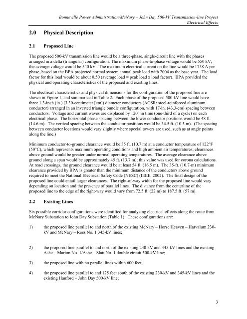
- Page 354 and 355: 1.0 Introduction Bonneville Power A
- Page 358 and 359: Bonneville Power Administration/McN
- Page 360 and 361: Bonneville Power Administration/McN
- Page 362 and 363: Bonneville Power Administration/McN
- Page 364 and 365: Bonneville Power Administration/McN
- Page 366 and 367: Bonneville Power Administration/McN
- Page 368 and 369: Bonneville Power Administration/McN
- Page 370 and 371: Bonneville Power Administration/McN
- Page 372 and 373: Bonneville Power Administration/McN
- Page 374 and 375: Bonneville Power Administration/McN
- Page 376 and 377: Bonneville Power Administration/McN
- Page 378 and 379: Bonneville Power Administration/McN
- Page 380 and 381: List of References Cited Bonneville
- Page 382 and 383: Bonneville Power Administration/McN
- Page 384 and 385: List of Preparers Bonneville Power
- Page 386 and 387: Bonneville Power Administration/McN
- Page 388 and 389: Table 2, continued Bonneville Power
- Page 390 and 391: Table 2, continued Bonneville Power
- Page 392 and 393: Bonneville Power Administration/McN
- Page 394 and 395: Bonneville Power Administration/McN
- Page 396 and 397: Bonneville Power Administration/McN
- Page 398 and 399: Bonneville Power Administration/McN
- Page 400 and 401: Figure 1, continued c) Proposed lin
- Page 402 and 403: Figure 1, continued Bonneville Powe
- Page 404 and 405: Bonneville Power Administration/McN
- Page 406 and 407:
Figure 2, continued Bonneville Powe
- Page 408 and 409:
Bonneville Power Administration/McN
- Page 410 and 411:
Figure 3, continued Bonneville Powe
- Page 412 and 413:
Bonneville Power Administration/McN
- Page 414 and 415:
Figure 4, continued Bonneville Powe
- Page 416 and 417:
Index 1 100-year floodplain .......
- Page 418 and 419:
Glade Creek.......S-9, S-12, 3-8, 3
- Page 420 and 421:
scoping .................S-7, 1-4,


