Section 3.10: Site Plans and Technical Data - Rick Neufeld Comments
Section 3.10: Site Plans and Technical Data - Rick Neufeld Comments
Section 3.10: Site Plans and Technical Data - Rick Neufeld Comments

You also want an ePaper? Increase the reach of your titles
YUMPU automatically turns print PDFs into web optimized ePapers that Google loves.
Northern Gateway Pipelines Inc.<br />
<strong>Section</strong> <strong>3.10</strong>: <strong>Site</strong> <strong>Plans</strong> <strong>and</strong> <strong>Technical</strong> <strong>Data</strong><br />
Table of Contents<br />
4 Design, Operating <strong>and</strong> Safety Parameters<br />
4.1 Design Vessels<br />
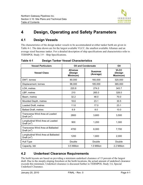
The characteristics of the design tanker vessels to be accommodated at either tanker berth are given in<br />
Table 4-1. The data shown are for the largest available VLCC, the smallest available Aframax <strong>and</strong> an<br />
average sized Suezmax tanker. For a detailed description of ship specifications <strong>and</strong> characteristics refer to<br />
TERMPOL Study 3.9 – Ship Specifications.<br />
Table 4-1 Design Tanker Vessel Characteristics<br />
Vessel Particulars Oil <strong>and</strong> Condensate Oil<br />
Vessel Class<br />
Aframax<br />
(Design<br />
Minimum)<br />
Suezmax<br />
(Average)<br />
VLCC<br />
(Design<br />
Maximum)<br />
DWT, tonnes 80,000 160,000 320,000<br />
Displacement, tonnes 96,000 185,000 365,000<br />
LOA, metres 220.8 274.0 343.7<br />
LBP, metres 210 265.0 328.0<br />
Beam, metres 32.2 48.0 70.0<br />
Moulded Depth, metres 18.6 23.1 30.5<br />
Loaded Draft, metres 11.6 17.0 23.1<br />
Ballast Draft, metres 6.9 8.0 10.0<br />
Transverse Wind Area at Loaded<br />
Draft (m 2 )<br />
Longitudinal Wind Area at Loaded<br />
Draft (m 2 )<br />
Transverse Wind Area at Ballasted<br />
Draft (m 2 )<br />
Longitudinal Wind Area at Ballasted<br />
Draft (m 2 )<br />
2800 3,600 3,500<br />
900 1,200 1,300<br />
4700 6,000 7,700<br />
1200 1,600 2,000<br />
Hull Type Double Double Double<br />
Capacity, bbl 0.5 Million 1.0 Million 2.2 Million<br />
4.2 Underkeel Clearance Requirements<br />
The berth layouts are based on providing a minimum underkeel clearance of 15 percent of the largest<br />
draft. Due to the steeply-sloping foreshore at the berth locations, the actual amount of underkeel clearance<br />
exceeds this minimum. Underkeel clearance is discussed further in TERMPOL Study 3.6, Special<br />
Underkeel Clearance.<br />
January 20, 2010 FINAL - Rev. 0 Page 4-1