

Through-Wall Imaging With UWB Radar System - KEMT FEI TUKE
Through-Wall Imaging With UWB Radar System - KEMT FEI TUKE
Through-Wall Imaging With UWB Radar System - KEMT FEI TUKE

Create successful ePaper yourself
Turn your PDF publications into a flip-book with our unique Google optimized e-Paper software.
2.1 <strong>UWB</strong> <strong>Radar</strong> systems 6<br />
2.1.2 <strong>UWB</strong> <strong>Radar</strong> Fundamentals<br />
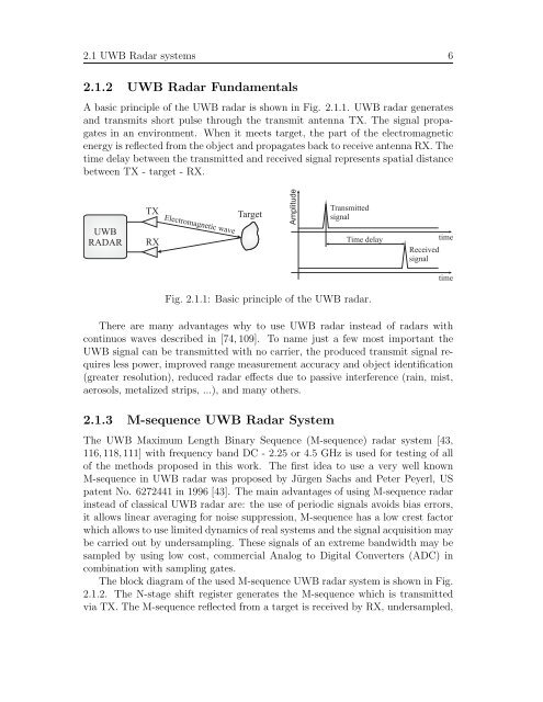
A basic principle of the <strong>UWB</strong> radar is shown in Fig. 2.1.1. <strong>UWB</strong> radar generates<br />
and transmits short pulse through the transmit antenna TX. The signal propagates<br />
in an environment. When it meets target, the part of the electromagnetic<br />
energy is reflected from the object and propagates back to receive antenna RX. The<br />
time delay between the transmitted and received signal represents spatial distance<br />
between TX - target - RX.<br />
<strong>UWB</strong><br />
RADAR<br />
TX<br />
RX<br />
Electromagnetic wave<br />
Target<br />
Amplitude<br />
Transmitted<br />
signal<br />
Time delay<br />
Fig. 2.1.1: Basic principle of the <strong>UWB</strong> radar.<br />
Received<br />
signal<br />
There are many advantages why to use <strong>UWB</strong> radar instead of radars with<br />
continuos waves described in [74, 109]. To name just a few most important the<br />
<strong>UWB</strong> signal can be transmitted with no carrier, the produced transmit signal requires<br />
less power, improved range measurement accuracy and object identification<br />
(greater resolution), reduced radar effects due to passive interference (rain, mist,<br />
aerosols, metalized strips, ...), and many others.<br />
2.1.3 M-sequence <strong>UWB</strong> <strong>Radar</strong> <strong>System</strong><br />
The <strong>UWB</strong> Maximum Length Binary Sequence (M-sequence) radar system [43,<br />
116, 118, 111] with frequency band DC - 2.25 or 4.5 GHz is used for testing of all<br />
of the methods proposed in this work. The first idea to use a very well known<br />
M-sequence in <strong>UWB</strong> radar was proposed by Jürgen Sachs and Peter Peyerl, US<br />
patent No. 6272441 in 1996 [43]. The main advantages of using M-sequence radar<br />
instead of classical <strong>UWB</strong> radar are: the use of periodic signals avoids bias errors,<br />
it allows linear averaging for noise suppression, M-sequence has a low crest factor<br />
which allows to use limited dynamics of real systems and the signal acquisition may<br />
be carried out by undersampling. These signals of an extreme bandwidth may be<br />
sampled by using low cost, commercial Analog to Digital Converters (ADC) in<br />
combination with sampling gates.<br />
The block diagram of the used M-sequence <strong>UWB</strong> radar system is shown in Fig.<br />
2.1.2. The N-stage shift register generates the M-sequence which is transmitted<br />
via TX. The M-sequence reflected from a target is received by RX, undersampled,<br />
time<br />
time


