

Through-Wall Imaging With UWB Radar System - KEMT FEI TUKE
Through-Wall Imaging With UWB Radar System - KEMT FEI TUKE
Through-Wall Imaging With UWB Radar System - KEMT FEI TUKE

You also want an ePaper? Increase the reach of your titles
YUMPU automatically turns print PDFs into web optimized ePapers that Google loves.
4.2 Measurements of the <strong>Wall</strong> Parameters by Reflectometry 62<br />
Propagation time [ns]<br />
17.7<br />
22.2<br />
26.6<br />
31.1<br />
35.5<br />
40.0<br />
44.4<br />
48.8<br />
<strong>Wall</strong>-Air interface<br />
Next wall<br />
out of interest<br />
Air-<strong>Wall</strong> interface<br />
50 100 150 200 250 300 350 400<br />
Propagation time [ns]<br />
4.4<br />
8.8<br />
13.3<br />
17.7<br />
22.2<br />
26.6<br />
Next wall<br />
out of interest<br />
<strong>Wall</strong>-Air interface<br />
Air-<strong>Wall</strong> interface<br />
Clutters<br />
50 100 150 200 250<br />
Number of impulse responses<br />
Number of impulse responses<br />
a) Measured data without crosstalk b) After synchronization and normalization<br />
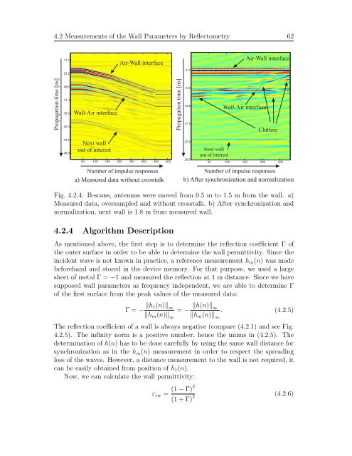
Fig. 4.2.4: B-scans, antennas were moved from 0.5 m to 1.5 m from the wall. a)<br />
Measured data, oversampled and without crosstalk. b) After synchronization and<br />
normalization, next wall is 1.8 m from measured wall.<br />
4.2.4 Algorithm Description<br />
As mentioned above, the first step is to determine the reflection coefficient Γ of<br />
the outer surface in order to be able to determine the wall permittivity. Since the<br />
incident wave is not known in practice, a reference measurement hm(n) was made<br />
beforehand and stored in the device memory. For that purpose, we used a large<br />
sheet of metal Γ = −1 and measured the reflection at 1 m distance. Since we have<br />
supposed wall parameters as frequency independent, we are able to determine Γ<br />
of the first surface from the peak values of the measured data:<br />
Γ = − �h1(n)� ∞<br />
�hm(n)� ∞<br />
= − �h(n)�∞ . (4.2.5)<br />
�hm(n)�∞ The reflection coefficient of a wall is always negative (compare (4.2.1) and see Fig.<br />
4.2.5). The infinity norm is a positive number, hence the minus in (4.2.5). The<br />
determination of h(n) has to be done carefully by using the same wall distance for<br />
synchronization as in the hm(n) measurement in order to respect the spreading<br />
loss of the waves. However, a distance measurement to the wall is not required, it<br />
can be easily obtained from position of h1(n).<br />
Now, we can calculate the wall permittivity:<br />
εrw =<br />
(1 − Γ)2<br />
(1 + Γ) 2<br />
(4.2.6)


