

Through-Wall Imaging With UWB Radar System - KEMT FEI TUKE
Through-Wall Imaging With UWB Radar System - KEMT FEI TUKE
Through-Wall Imaging With UWB Radar System - KEMT FEI TUKE

You also want an ePaper? Increase the reach of your titles
YUMPU automatically turns print PDFs into web optimized ePapers that Google loves.
2.5 <strong>Radar</strong> <strong>Imaging</strong> Methods Overview 28<br />
�( xz , �0,<br />
t)<br />
�( xzt , , �0)<br />
2D FFT<br />
�( xz , �0, t) ��<br />
( k, f)<br />
vk<br />
z<br />
k � k<br />
2 2<br />
x z<br />
2D Inverse FFT<br />
0<br />
0<br />
� ( k , f) ��( x, z, t �0)<br />
x<br />
x<br />
Interpolation / Mapping<br />
f<br />
k k<br />
v<br />
z �<br />
2<br />
� 2<br />
2<br />
x<br />
Multiplication<br />
vk / k � k<br />
2 2<br />
z x z<br />
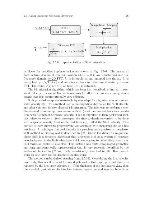
Fig. 2.5.6: Implementation of Stolt migration.<br />
in blocks for practical implementation are shown in Fig. 2.5.6. The measured<br />
data in time domain at receiver position ψ(x, z = 0, t) are transformed into the<br />
frequency domain by 2D FFT. kx is interpolated and mapped into the kz. kz is<br />
multiplied by v/ � k 2 x + k 2 z and transformed back into the time domain by inverse<br />
FFT. The result ψ(x, z, t = 0) at time t = 0 is obtained.<br />
The f-k migration algorithm, which has been just described, is limited to constant<br />
velocity. Its use of Fourier transforms for all of the numerical integrations<br />
means that it is computationally very efficient.<br />
Stolt provided an approximate technique to adapt f-k migration to non constant<br />
wave velocity v(z). This method used a pre-migration step called the Stolt stretch,<br />
and after this step follows classical f-k migration. The idea was to perform a onedimensional<br />
time-to-depth conversion with v(z) and then convert back to a pseudo<br />
time with a constant reference velocity. The f-k migration is then performed with<br />
this reference velocity. Stolt developed the time-to-depth conversion to be done<br />
with a special velocity function derived from v(z) called the Stolt velocity. This<br />
method is now known to progressively lose accuracy with increasing dip and has<br />
lost favor. A technique that could handle this problem more precisely is the phaseshift<br />
method of Gazdag and is described in [62]. Unlike the direct f-k migration,<br />
phase shift is a recursive algorithm that processes v(z) as a system of constant<br />
velocity layers. In the limit when layer thickness is going to be infinitely small, any<br />
v(z) variation could be modeled. This method has quite complicated geometric<br />
and long mathematically representation that is very precisely described by the<br />
author of the idea in [62] and really user-friendly described in [96]. How does it<br />
work for one layer will be described in this work.<br />
The method can be derived starting from (2.5.39). Considering the first velocity<br />
layer only, this result is valid for any depth within that layer provided that v is<br />
replaced by the first layer velocity, v1. If the thickness of the first layer is ∆z1, then<br />
the wavefield just above the interface between layers one and two can be written


