

Through-Wall Imaging With UWB Radar System - KEMT FEI TUKE
Through-Wall Imaging With UWB Radar System - KEMT FEI TUKE
Through-Wall Imaging With UWB Radar System - KEMT FEI TUKE

Create successful ePaper yourself
Turn your PDF publications into a flip-book with our unique Google optimized e-Paper software.
2.4 Calibration and Preprocessing 10<br />
Z<br />
SXZ ( , )<br />
Motion<br />
X<br />
TX RX<br />
TX RX<br />
tr tr [ x,z re re]<br />
[ x,z]<br />
E 1<br />
T= [ x T,zT] E 2<br />
n<br />
BXn ( , )<br />
Hyperbola<br />
a) b)<br />
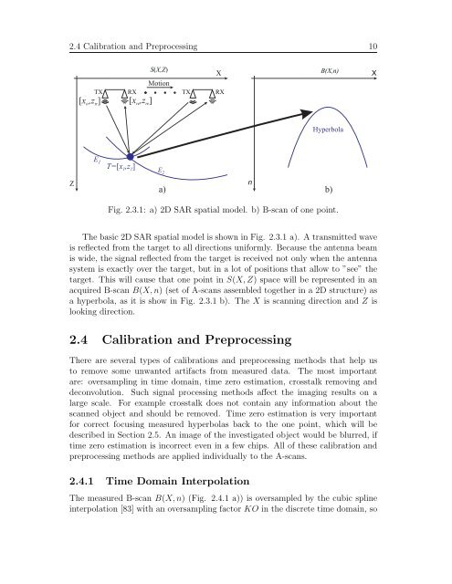
Fig. 2.3.1: a) 2D SAR spatial model. b) B-scan of one point.<br />
The basic 2D SAR spatial model is shown in Fig. 2.3.1 a). A transmitted wave<br />
is reflected from the target to all directions uniformly. Because the antenna beam<br />
is wide, the signal reflected from the target is received not only when the antenna<br />
system is exactly over the target, but in a lot of positions that allow to ”see” the<br />
target. This will cause that one point in S(X, Z) space will be represented in an<br />
acquired B-scan B(X, n) (set of A-scans assembled together in a 2D structure) as<br />
a hyperbola, as it is show in Fig. 2.3.1 b). The X is scanning direction and Z is<br />
looking direction.<br />
2.4 Calibration and Preprocessing<br />
There are several types of calibrations and preprocessing methods that help us<br />
to remove some unwanted artifacts from measured data. The most important<br />
are: oversampling in time domain, time zero estimation, crosstalk removing and<br />
deconvolution. Such signal processing methods affect the imaging results on a<br />
large scale. For example crosstalk does not contain any information about the<br />
scanned object and should be removed. Time zero estimation is very important<br />
for correct focusing measured hyperbolas back to the one point, which will be<br />
described in Section 2.5. An image of the investigated object would be blurred, if<br />
time zero estimation is incorrect even in a few chips. All of these calibration and<br />
preprocessing methods are applied individually to the A-scans.<br />
2.4.1 Time Domain Interpolation<br />
The measured B-scan B(X, n) (Fig. 2.4.1 a)) is oversampled by the cubic spline<br />
interpolation [83] with an oversampling factor KO in the discrete time domain, so<br />
X


