

Through-Wall Imaging With UWB Radar System - KEMT FEI TUKE
Through-Wall Imaging With UWB Radar System - KEMT FEI TUKE
Through-Wall Imaging With UWB Radar System - KEMT FEI TUKE

Create successful ePaper yourself
Turn your PDF publications into a flip-book with our unique Google optimized e-Paper software.
2.2 <strong>Through</strong>-<strong>Wall</strong> <strong>Radar</strong> Basic Model 8<br />
a) b)<br />
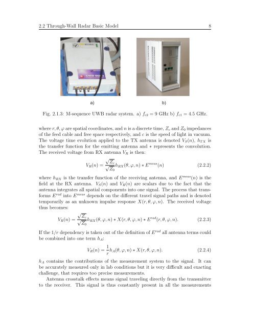
Fig. 2.1.3: M-sequence <strong>UWB</strong> radar system. a) fc2 = 9 GHz b) fc1 = 4.5 GHz.<br />
where r, θ, ϕ are spatial coordinates, and n is a discrete time, Zc and Z0 impedances<br />
of the feed cable and free space respectively, and c is the speed of light in vacuum.<br />
The voltage time evolution applied to the TX antenna is denoted VS(n), hT X is<br />
the transfer function for the emitting antenna and ∗ represents the convolution.<br />
The received voltage from RX antenna VR is then:<br />
VR(n) =<br />
√ Zc<br />
√ hRX(θ, ϕ, n) ∗ E<br />
Z0<br />
meas (n) (2.2.2)<br />
where hRX is the transfer function of the receiving antenna, and E meas (n) is the<br />
field at the RX antenna. VS(n) and VR(n) are scalars due to the fact that the<br />
antenna integrates all spatial components into one signal. The process that transforms<br />
E rad into E meas depends on the different travel signal paths and is denoted<br />
temporarily as an unknown impulse response X(r, θ, ϕ, n). The received voltage<br />
thus becomes:<br />
VR(n) =<br />
√ Zc<br />
√ hRX(θ, ϕ, n) ∗ X(r, θ, ϕ, n) ∗ E<br />
Z0<br />
rad (r, θ, ϕ, n). (2.2.3)<br />
If the 1/r dependency is taken out of the definition of E rad all antenna terms could<br />
be combined into one term hA:<br />
VR(n) = 1<br />
r hA(θ, ϕ, n) ∗ X(r, θ, ϕ, n). (2.2.4)<br />
hA contains the contributions of the measurement system to the signal. It can<br />
be accurately measured only in lab conditions but it is very difficult and exacting<br />
challenge, that requires too precise measurements.<br />
Antenna crosstalk effects means signal traveling directly from the transmitter<br />
to the receiver. This signal is thus constantly present in all the measurements


