

Through-Wall Imaging With UWB Radar System - KEMT FEI TUKE
Through-Wall Imaging With UWB Radar System - KEMT FEI TUKE
Through-Wall Imaging With UWB Radar System - KEMT FEI TUKE

You also want an ePaper? Increase the reach of your titles
YUMPU automatically turns print PDFs into web optimized ePapers that Google loves.
2.4 Calibration and Preprocessing 13<br />
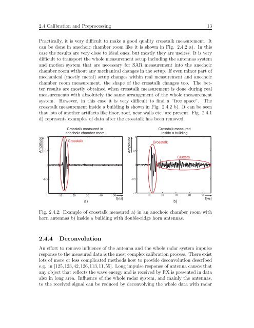
Practically, it is very difficult to make a good quality crosstalk measurement. It<br />
can be done in anechoic chamber room like it is shown in Fig. 2.4.2 a). In this<br />
case the results are very close to ideal ones, but mostly they are useless. It is very<br />
difficult to transport the whole measurement setup including the antennas system<br />
and motion system that are necessary for SAR measurement into the anechoic<br />
chamber room without any mechanical changes in the setup. If even minor part of<br />
mechanical (mostly metal) setup changes within real measurement and anechoic<br />
chamber room measurement, the shape of the crosstalk changes too. The better<br />
results are mostly obtained when crosstalk measurement is done during real<br />
measurements with absolutely the same arrangement of the whole measurement<br />
system. However, in this case it is very difficult to find a ”free space”. The<br />
crosstalk measurement inside a building is shown in Fig. 2.4.2 b). It can be seen<br />
that lots of another artifacts like floor, roof, near walls etc. are present. Fig. 2.4.1<br />
d) represents examples of data after the crosstalk has been removed.<br />
Amplitude<br />
1<br />
0.5<br />
0<br />
-1<br />
Crosstalk measured in<br />
anechoic chamber room<br />
Crosstalk<br />
Amplitude<br />
1<br />
0.5<br />
0<br />
Crosstalk measured<br />
inside a building<br />
Crosstalk<br />
-1<br />
10 20 30 40 50<br />
10 20 30 40 50<br />
tns [ ] tns [ ]<br />
a) b)<br />
Clutters<br />
Fig. 2.4.2: Example of crosstalk measured a) in an anechoic chamber room with<br />
horn antennas b) inside a building with double-ridge horn antennas.<br />
2.4.4 Deconvolution<br />
An effort to remove influence of the antenna and the whole radar system impulse<br />
response to the measured data is the most complex calibration process. There exist<br />
lots of more or less complicated methods how to provide deconvolution described<br />
e.g. in [125,123,42,126,113,11,55]. Long impulse response of antenna causes that<br />
any object that reflects the wave energy and is received by RX is presented in data<br />
also in long area. Influence of the whole radar system, and mainly the antennas,<br />
to the received signal can be reduced by deconvolving the whole data with radar


