D10: Impact of Contaminants - Hydromod
D10: Impact of Contaminants - Hydromod
D10: Impact of Contaminants - Hydromod

Create successful ePaper yourself
Turn your PDF publications into a flip-book with our unique Google optimized e-Paper software.
Integrated Water Resource Management for Important Deep European Lakes and their Catchment Areas<br />
EUROLAKES<br />
<strong>D10</strong>: <strong>Impact</strong> <strong>of</strong> <strong>Contaminants</strong><br />
FP5_Contract No.: EVK1-CT1999-00004<br />
Version: 4.0<br />
Date: 25/07/01<br />
File: <strong>D10</strong>-vers.4.0.doc<br />
Page 96 <strong>of</strong> 136<br />
Anaerobic digestion<br />
In an anaerobic digester the organic material is metabolised into approx. 2 /3 CH4, 1 /3<br />
CO2 and biomass. The process is performed in a stirred reactor at a temperature between<br />
30-37 °C. The gas can be used for heating or energy generation. After anaerobic<br />
digestion the stabilised sludge is thickened to the extent required for the final disposal.<br />
Aerobic stabilisation<br />
Excess sludge can also be stabilised aerobically by increasing the aerobic sludge age<br />
to an extent where organic material is aerobically degraded and mineralised. This is<br />
practically done simultaneously in the aeration tank in small plants (up to 10.000 P.E),<br />
or in a separate aerated stabilisation basin. The aerobic stabilisation process is much<br />
more energy consuming than anaerobic fermentation. Also the de-watering <strong>of</strong> the aerobically<br />
stabilised sludge is more difficult and energy consuming. For this reason aerobic<br />
stabilisation is only applied in small treatment plants. (up to 10.000 – 25.000 PE).<br />
Supernatant liquids and process water<br />
The supernatant liquids from all processes for thickening (static thickeners, mechanical<br />
de-watering) are usually charged with high loads <strong>of</strong> nutrients and also COD. For that<br />
reason different strategies for adding the waters to the plant or even for separate treatment<br />
are applied.<br />
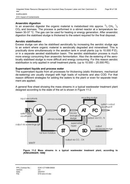
A general flow sheet showing the mass streams in a typical wastewater treatment plant<br />
designed according to the state <strong>of</strong> the art is shown in Figure 11-2<br />
Figure 11-2 Mass streams in a typical wastewater treatment plant, according to<br />
[KREUZINGER, 1998]