estudio y caracterización de un plasma de microondas a presión ...
estudio y caracterización de un plasma de microondas a presión ...
estudio y caracterización de un plasma de microondas a presión ...

You also want an ePaper? Increase the reach of your titles
YUMPU automatically turns print PDFs into web optimized ePapers that Google loves.
Destrucción <strong>de</strong> VOCs con <strong>plasma</strong> <strong>de</strong> Aire<br />
124<br />
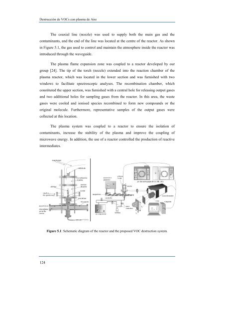
The coaxial line (nozzle) was used to supply both the main gas and the<br />
contaminants, and the end of the line was located at the centre of the reactor. As shown<br />
in Figure 5.1, the gas used to control and maintain the atmosphere insi<strong>de</strong> the reactor was<br />
introduced through the wavegui<strong>de</strong>.<br />
The <strong>plasma</strong> flame expansion zone was coupled to a reactor <strong>de</strong>veloped by our<br />
group [24]. The tip of the torch (nozzle) exten<strong>de</strong>d into the reaction chamber of the<br />
<strong>plasma</strong> reactor, which was located in the lower section and was furnished with two<br />
windows to facilitate spectroscopic analyses. The recombination chamber, which<br />
constituted the upper section, was furnished with a central hole for releasing output gases<br />
and two additional holes for sampling gases from the reactor. In this area, the waste<br />
gases were cooled and ionised species recombined to form new compo<strong>un</strong>ds or the<br />
original molecule. Furthermore, representative samples of the output gases were<br />
collected at this location.<br />
The <strong>plasma</strong> system was coupled to a reactor to ensure the isolation of<br />
contaminants, increase the stability of the <strong>plasma</strong> and improve the coupling of<br />
microwave energy. In addition, the use of a reactor controlled the production of reactive<br />
intermediates.<br />
Figure 5.1: Schematic diagram of the reactor and the proposed VOC <strong>de</strong>struction system.