Montageanlöeitung/Bedienungsanleitung / Assembly instruction ...
Montageanlöeitung/Bedienungsanleitung / Assembly instruction ...
Montageanlöeitung/Bedienungsanleitung / Assembly instruction ...

You also want an ePaper? Increase the reach of your titles
YUMPU automatically turns print PDFs into web optimized ePapers that Google loves.
5.2.3 Fault Signalling Facility<br />
All faults on the cooling unit are registered and<br />
indicated by H1 as a fault number. The display is<br />
by means of the left-hand number. The display<br />
cycles through all pending fault messages in a<br />
2 second cycle, starting with the internal temperature<br />
of the enclosure.<br />
H1 indicates the following faults as a fault number.<br />
1 = Enclosure internal temperature too high<br />
(5 K above setpoint value)<br />
2 = Current monitor, condenser<br />
3 = Evaporator (no collective fault indication).<br />
4 = High-pressure monitor<br />
5 = Current monitor, condenser fan<br />
6 = Current monitor, evaporator fan<br />
7 = Filter mat soiled<br />
8 = Temperature sensor cable break/short-circuit<br />
5.2.3.1 Fault Signal Contact<br />
(K1, potential-free)<br />
The fault signal relay is pulled in at normal condition.<br />
Any faults will cause the relay to drop out<br />
(except low-pressure monitor, fault number 3).<br />
Any failure of the control voltage will also lead to<br />
drop-out of the relay and can thus be registered.<br />
The connection is made on the terminal strip X10.<br />
For contact data and assignment, see wiring diagram.<br />
5.2.3.2 Filter Mat Monitoring<br />
The specified filter mat has large pores and filters<br />
coarse dust and lint from the air. Oil condensate is<br />
partially separated out. Fine dust is drawn through<br />
the filter mat and the external circuit of the unit<br />
due to the high suction power of the fan. It does<br />
not have any damaging effect on the function of<br />
the unit.<br />
Fig. 5.3 Filter Mat Replacement<br />
1<br />
°C TEST ENTER<br />
°F<br />
32<br />
SK 3395.... SK 3255....<br />
2<br />
5.2.3.3 Door Limit Switch S 2<br />
(supplied by costumer)<br />
Where a door limit switch is used and the enclosure<br />
door is open (contact is closed when door is<br />
open), the cooling unit (fans and condenser) will<br />
switch off after approx. 10 s, thereby avoiding an<br />
increase in condensation while the door is open.<br />
To avoid cyclic operation, switch-on of condenser<br />
and external fan is delayed by about 3 minutes<br />
after the door has been closed. The internal fan<br />
will start up immediately on closure of the door.<br />
Connection is made at the terminal strip X10, terminals<br />
1 and 2. The extra low voltage is supplied<br />
by the internal power pack, current is approx.<br />
30 mA DC (no extra low safety voltage). Connect<br />
the door limit switch free from potential only, no<br />
external voltage! The display will flash during the<br />
door delay time. The system message “1010” is<br />
transmitted via the PLC interface.<br />
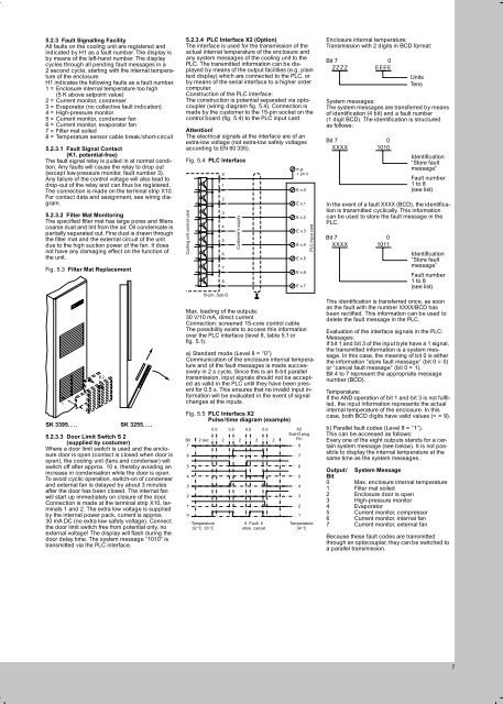
5.2.3.4 PLC Interface X2 (Option)<br />
The interface is used for the transmission of the<br />
actual internal temperature of the enclosure and<br />
any system messages of the cooling unit to the<br />
PLC. The transmitted information can be displayed<br />
by means of the output facilities (e.g. plain<br />
text display) which are connected to the PLC, or<br />
by means of the serial interface to a higher order<br />
computer.<br />
Construction of the PLC interface:<br />
The construction is potential separated via optocoupler<br />
(wiring diagram fig. 5.4). Connection is<br />
made by the customer to the 15-pin socket on the<br />
control board (fig. 5.4) to the PLC input card.<br />
Attention!<br />
The electrical signals at the interface are of an<br />
extra-low voltage (not extra-low safety voltages<br />
according to EN 60 335).<br />
Fig. 5.4 PLC Interface<br />
Cooling unit control card<br />
5<br />
4<br />
3<br />
2<br />
1<br />
0<br />
9<br />
1<br />
2<br />
3<br />
4<br />
5<br />
6<br />
7<br />
8<br />
15-pin. Sub-D<br />
Customer’s supply<br />
e.g.<br />
+ 24 V<br />
E x.0<br />
E x.1<br />
E x.2<br />
E x.3<br />
E x.4<br />
E x.5<br />
E x.6<br />
E x.7<br />
Max. loading of the outputs:<br />
30 V/10 mA, direct current<br />
Connection: screened 15-core control cable<br />
The possibility exists to access this information<br />
over the PLC interface (level 8, table 5.1 or<br />
fig. 5.1).<br />
a) Standard mode (Level 8 = “0”)<br />
Communication of the enclosure internal temperature<br />
and of the fault messages is made successively<br />
in 2 s cycle. Since this is an 8-bit parallel<br />
transmission, input signals should not be accepted<br />
as valid in the PLC until they have been present<br />
for 0.5 s. This ensures that no invalid input information<br />
will be evaluated in the event of signal<br />
changes at the inputs.<br />
Fig. 5.5 PLC Interface X2<br />
Pulse/time diagram (example)<br />
0.5 0.5 0.5 0.5 X2<br />
Sub-D plug<br />
Bit 2 sec. 2 2 2 2<br />
Pin<br />
7<br />
8<br />
6<br />
7<br />
Temperature<br />
32 °C 33 °C<br />
5 Fault 6<br />
store cancel<br />
6<br />
5<br />
4<br />
3<br />
2<br />
1<br />
PLC input card<br />
Temperature<br />
34 °C<br />
Enclosure internal temperature:<br />
Transmission with 2 digits in BCD format:<br />
Bit 7<br />
0<br />
ZZZZ EEEE<br />
System messages:<br />
The system messages are transferred by means<br />
of identification (4 bit) and a fault number<br />
(1 digit BCD). The identification is structured<br />
as follows:<br />
Bit 7<br />
0<br />
XXXX 1010<br />
Units<br />
Tens<br />
Fault number<br />
1 to 8<br />
(see list)<br />
In the event of a fault XXXX (BCD), the identification<br />
is transmitted cyclically. This information<br />
can be used to store the fault message in the<br />
PLC.<br />
Bit 7<br />
0<br />
XXXX 1011<br />
Identification<br />
“Store fault<br />
message”<br />
Identification<br />
“Store fault<br />
message”<br />
Fault number<br />
1 to 8<br />
(see list)<br />
This identification is transferred once, as soon<br />
as the fault with the number XXXX/BCD has<br />
been rectified. This information can be used to<br />
delete the fault message in the PLC.<br />
Evaluation of the interface signals in the PLC:<br />
Messages:<br />
If bit 1 and bit 3 of the input byte have a 1 signal,<br />
the transmitted information is a system message.<br />
In this case, the meaning of bit 0 is either<br />
the information “store fault message” (bit 0 = 0)<br />
or “cancel fault message” (bit 0 = 1).<br />
Bit 4 to 7 represent the appropriate message<br />
number (BCD).<br />
Temperature:<br />
If the AND operation of bit 1 and bit 3 is not fulfilled,<br />
the input information represents the actual<br />
internal temperature of the enclosure. In this<br />
case, both BCD digits have valid values (< = 9).<br />
b) Parallel fault codes (Level 8 = “1”).<br />
This can be accessed as follows:<br />
Every one of the eight outputs stands for a certain<br />
system message (see below). It is not possible<br />
to display the internal temperature at the<br />
same time as the system messages.<br />
Output/ System Message<br />
Bit<br />
0 Max. enclosure internal temperature<br />
1 Filter mat soiled<br />
2 Enclosure door is open<br />
3 High-pressure monitor<br />
4 Evaporator<br />
5 Current monitor, compressor<br />
6 Current monitor, internal fan<br />
7 Current monitor, external fan<br />
Because these fault codes are transmitted<br />
through an optocoupler, they can be switched to<br />
a parallel transmission.<br />
7