ED 3 M HS - DAB Pumps S.p.a.
ED 3 M HS - DAB Pumps S.p.a.
ED 3 M HS - DAB Pumps S.p.a.

Create successful ePaper yourself
Turn your PDF publications into a flip-book with our unique Google optimized e-Paper software.
9.<br />
ENGLISH<br />
<strong>ED</strong> 1 T-<strong>ED</strong> 1,5 T-<strong>ED</strong> 2,5 T-<strong>ED</strong> 4 T-<strong>ED</strong> 7,5 T-<strong>ED</strong> 8 T-<strong>ED</strong> 15 T SD-<strong>ED</strong> 20 T SD- <strong>ED</strong> 25T<br />
SD – <strong>ED</strong> 30 T SD<br />
9.1 Technical data<br />
�� rated input voltage: 400 V +/- 10%<br />
�� phases: 3<br />
�� frequency: 50-60 Hz<br />
<strong>ED</strong> 1 T <strong>ED</strong> 1,5 T <strong>ED</strong> 2,5 T <strong>ED</strong> 4 T <strong>ED</strong> 7,5 T <strong>ED</strong> 8 T<br />
�� max. rated output power (KW): 1,38 2,2 3,5 5,5 7,7 9,9<br />
�� max. rated using current (A): 2,5 4 6,3 10 14 18<br />
<strong>ED</strong> 15 T SD <strong>ED</strong> 20 T SD <strong>ED</strong> 25 T SD <strong>ED</strong> 30 T SD<br />
�� max. rated output power (KW): 13,8 17,7 18,5 22<br />
�� max. rated using current (A): 25 32 40 63<br />
�� field of use environment temperature: -10°C +40°C<br />
�� storage environment temp. limit: -25°C +55°C<br />
�� relative humidity (without condensation): 50% at 40°C MAX (90% at 20°C )<br />
�� max. altitude: 3000 m (a.s.l.)<br />
�� degree of protection: IP55<br />
�� panel construction: in accordance with EN 60204-1 and EN 60439-1<br />
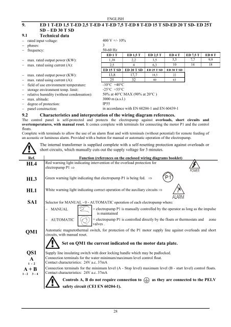
9.2 Characteristics and interpretation of the wiring diagram references.<br />
The control panel is self-protected and protects the electropump against overloads, short circuits and<br />
overtemperatures, with manual reset. It comes complete with terminals for connecting the motor P1 and the control<br />
floats.<br />
Complete with terminals to allow the use of an alarm float and with terminals (without potential) for remote feeding of<br />
an acoustic or luminous alarm. Provided with a button for manual or automatic operation of the electropump.<br />
The internal transformer is supplied complete with a self-resetting protection against overloads or<br />
short circuits, which manually cuts out the supply voltage for 3 minutes.<br />
Ref. Function (references on the enclosed wiring diagrams booklet)<br />
Red warning light indicating intervention of the overload protection for<br />
electropump P1 ��<br />
HL4<br />
HL3<br />
HL1<br />
SA1<br />
QM1<br />
QS1<br />
A<br />
1 - 2<br />
A + B<br />
1 - 2 __3 – 4<br />
Green warning light indicating that electropump P1 is being fed. ��<br />
�<br />
White warning light indicating correct operation of the auxiliary circuits ��<br />
������������������<br />
Selector for MANUAL - 0 - AUTOMATIC operation of each electropump where:<br />
�� MANUAL<br />
= electropump P1 is manually controlled by the operator as long as the impulse<br />
is maintained<br />
�� AUTOMATIC = electropump P1 is controlled directly by the floats or thermostats and zone<br />
valves .<br />
Automatic magnetothermal switch, for protection of the P1 motor supply line against overloads and short<br />
circuits, with manual reset.<br />
Set on QM1 the current indicated on the motor data plate.<br />
Supply line insulating switch with door locking handle which may be padlocked.<br />
Connection terminals for the water minimum/maximum level control float.<br />
Contact characteristics: 24V a.c. 37mA<br />
Connection terminals for the minimum level (A - Stop level) maximum level (B - start level) control floats.<br />
Contact characteristics: 24V a.c. 37mA<br />
Controls A, B do not require connection to<br />
safety circuit (CEI EN 60204-1).<br />
28<br />
as they are connected to the PELV