ED 3 M HS - DAB Pumps S.p.a.
ED 3 M HS - DAB Pumps S.p.a.
ED 3 M HS - DAB Pumps S.p.a.

You also want an ePaper? Increase the reach of your titles
YUMPU automatically turns print PDFs into web optimized ePapers that Google loves.
ENGLISH<br />
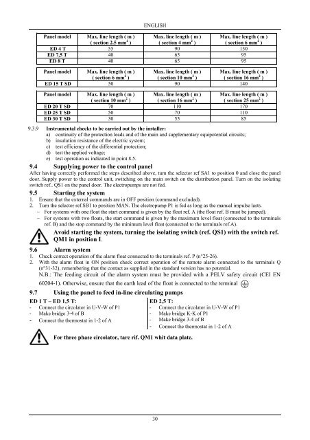
Panel model Max. line length ( m )<br />
( section 2.5 mm 2 Max. line length ( m )<br />
)<br />
( section 4 mm 2 Max. line length ( m )<br />
)<br />
( section 6 mm 2 )<br />
<strong>ED</strong> 4 T 55 90 130<br />
<strong>ED</strong> 7,5 T 40 65 95<br />
<strong>ED</strong> 8 T 40 65 95<br />
Panel model Max. line length ( m )<br />
( section 6 mm 2 Max. line length ( m )<br />
)<br />
( section 10 mm 2 Max. line length ( m )<br />
)<br />
( section 16 mm 2 )<br />
<strong>ED</strong> 15 T SD 50 90 140<br />
Panel model Max. line length ( m )<br />
( section 10 mm 2 Max. line length ( m )<br />
)<br />
( section 16 mm 2 Max. line length ( m )<br />
)<br />
( section 25 mm 2 )<br />
<strong>ED</strong> 20 T SD 70 110 170<br />
<strong>ED</strong> 25 T SD 50 70 110<br />
<strong>ED</strong> 30 T SD 30 55 85<br />
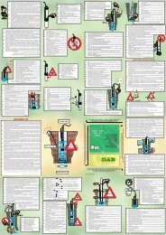
9.3.9 Instrumental checks to be carried out by the installer:<br />
a) continuity of the protection leads and of the main and supplementary equipotential circuits;<br />
b) insulation resistance of the electric system;<br />
c) test efficiency of the differential protection;<br />
d) test the applied voltage;<br />
e) test operation as indicated in point 8.5.<br />
9.4 Supplying power to the control panel<br />
After having correctly performed the steps described above, turn the selector ref SA1 to position 0 and close the panel<br />
door. Supply power to the control unit, switching on the main switch on the distribution panel. Turn on the isolating<br />
switch ref.. QS1 on the panel door. The electropumps are not fed.<br />
9.5 Starting the system<br />
1. Ensure that the external commands are in OFF position (command excluded).<br />
2. Turn the selector ref.SB1 to position MAN. The electropump P1 is fed as long as the manual impulse lasts.<br />
�� For systems with one float the start command is given by the float ref. A (the float ref. B must be jumped).<br />
�� For systems with two floats, the start command is given by the maximum level float (connected to the terminals<br />
ref. B) and the stop command by the minimum level float (connected to the terminals ref.A).<br />
Avoid starting the system, turning the isolating switch (ref. QS1) with the switch ref.<br />
QM1 in position I.<br />
9.6 Alarm system<br />
1. Check correct operation of the alarm float connected to the terminals ref. P (n°25-26).<br />
2. With the alarm float in ON position check correct operation of the remote alarm connected to the terminals Q<br />
(n°31-32), remembering that the contact as supplied in the standard version has no potential.<br />
N.B.: The feeding circuit of the alarm system must be provided with a PELV safety circuit (CEI EN<br />
60204-1). Otherwise, ensure that the earth lead of the float is connected to the terminal<br />
9.7 Using the panel to feed in-line circulating pumps<br />
<strong>ED</strong> 1 T – <strong>ED</strong> 1,5 T:<br />
- Connect the circolator in U-V-W of P1<br />
- Make bridge 3-4 of B<br />
- Connect the thermostat in 1-2 of A<br />
For three phase circolator, tare rif. QM1 whit data plate.<br />
<strong>ED</strong> 2,5 T:<br />
- Connect the circolator in U-V-W of P1<br />
- Make bridge K-K of P1<br />
- Make bridge 3-4 of B<br />
- Connect the thermostat in 1-2 of A<br />
30