Untitled - Revoxsammler
Untitled - Revoxsammler
Untitled - Revoxsammler

You also want an ePaper? Increase the reach of your titles
YUMPU automatically turns print PDFs into web optimized ePapers that Google loves.
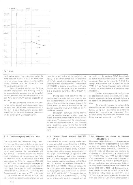
Fis.7.1.-5<br />
des Regeltransistors nahezu konstant bleibt. Die<br />
Amplitude von YAN-lV 1 ist zu der Steuerspannung<br />
U" proportional, jedoch sinus-halbwellenförmig.<br />
Dadurch wird der Strom Über dem<br />
Motor sinusförmig gesteuert.<br />
Beim Umspulen werden die Bandzugsensoren<br />
umgeschaltet. Der Bandzug wird auf<br />
der Aufwickelseite gemessen und die Abwickelseite<br />
so gesteuert, dass der Bandzug nicht unter<br />
den Wert, der im PLAY-Betrieb eingestellt ist,<br />
absi n kt.<br />
ln der Bremsphase wird der Abwickelmotor<br />
weiter geregelt und abgeschaltet, wenn<br />
das Band hält. Der zeitliche Steuerablauf wird in<br />
Fig. 7.1"-5 beim Fückwickeln gezeigt. Beim<br />
Vorwickeln ist der Ablauf derselbe, jedoch sollen<br />
die Signale an lC 3 gemessen werden.<br />
the collector and emitter of the regulating transistor,<br />
are so dimensionned that the amplltude<br />
of Y-FMB1 remains constant regardless of the<br />
transistor's state of conductivity. The amplitude<br />
of YAN-M1 is directly proportional to U" and<br />
consists also of half cycles only. As a result of<br />
this, a sinusoidal current will f low through the<br />
motor.<br />
During both wind operations the tape<br />
tension sensors are changed over in such a way<br />
that the tape tension, which is measured on the<br />
take-up side, controls the counter torque of the<br />
supply motor to avoid a reduction of the tape<br />
tension below the value which has been set for<br />
the PLAY function.<br />
Regulation continues during braking<br />
until the tape has stopped, at which point the<br />
supply of electric current to both motors will be<br />
interrupted. The sequence of the control signals<br />
for rewind is shown in figure 7.1.-5. The same<br />
signal conditions apply to the fast forward,<br />
mode except that all readings must be taken on<br />
rc 3.<br />
de conduction du transistor OPWR, l'amplitude<br />
du signal sinusoidal demi-onde Y-FBM 1 reste<br />
constante. C'est par le retour de Y-FMB 1 ä<br />
l'6tage multiplicateur que le signal de sortie<br />
YAN-M 1 de forme sinusoidale demi-onde est<br />
d'amplitude proportionelle ä la tension de commande<br />
U* .<br />
Pendant le bobinage rapide, la r6gulation<br />
du cötd d6biteur agit de telle faqon, que la position<br />
du tendeur de bande ne soit pas infdrieure ä<br />
sa position en enregistrement ou en reproduction.<br />
' En phase de freinage, le moteur de la<br />
bobine ddbitrice est contrö16 jusqu'ä l'arr6t de la<br />
bande. La fig. 7.1.-5 ddmontre ces diff6rentes<br />
phases de commande en rebobinage. Pour<br />
l'avance rapide, les phases sont les m6mes, seuls<br />
les signaux sont mesur6s alors par IC 3.<br />
7.1.6. Tonmotorregelung 1.067.235 (A15)<br />
Durch das induktive Tachometer ( Ringabtaster)<br />
wird eine zur Bandgeschwindigkeit proportionale<br />
Frequenz erzeugt. Sie wird durch die Eingangsschaltung<br />
mit lC 1 von Brummspannung<br />
befreit und begrenzt. Der nachfolgende lC2<br />
Typ TDA 1000 ist eine Frequenz- und Phasenvergleichschaltung<br />
mit quarzgesleuertem Referenzoszillator.<br />
lm lC werden durch exakte Frequenzteilung<br />
die Referenzfrequenzen (400, 800<br />
und 1600 Hz), die den Bandgeschwindigkeiten<br />
zugeordnet sind, erzeugt. Die Umschaltung erfolgt<br />
durch Steuerung der dafür vorgesehenen<br />
Anschlüsse an lC 2 (Punkt 14, 15 und 16). Das<br />
Ausgargssignal - gemessen an TP 1 - ist stetig<br />
"L" bei Hochlaufen des Motors, bis die Drehzahl<br />
erreicht ist. Nach Herunterschalten auf eine<br />
7.1.6<br />
7.1.6. Capstan Speed Control 1.067.235<br />
(A 15)<br />
ln the circular tachometric sensino head a signal<br />
is being generated, whose frequency is directly<br />
proportional to tape speed. In the input circuit<br />
of lC 1 that signal is strlpped of any hum components,<br />
after which it passes an amplitude limiting<br />
stage. The following lC 2, type TDA 1000,<br />
contains a frequency and phase comparator<br />
with a crystal equipped reference oscillator.<br />
Exact devider stages are contained in that lC as<br />
well, to provide the reference frequencies of<br />
400, 800 and 1600 Hz, which are assigned to<br />
the three tape speeds. Speed change is effected<br />
by changing the signal condition at the contact<br />
pins 1 4, 1 5 and 1 6 of lC 2. The output signal as<br />
measured at TP 1 is continuously "L" during<br />
run-up of the motor until the required rpm are<br />
7.1.6. R6gulateur de vitesse du cabestan<br />
1.067.235 (A15)<br />
Un anneau tachymdtrique inductif engendre un<br />
signal de frdquence proportionnelle au nombre<br />
de tours du moteur du cabestan. Ce signal est,<br />
par le circuit intögrd d'entrde lC 1 TBA 931-1,<br />
amplifi6, limit6 et d6barrassö des tensions de<br />
ronf lement. La rösistance R 13 le conduit au circuit<br />
intdgr6 lC 2, TDA 1000, qui est compos6<br />
d'un comparateur de phase et de fr6quence et<br />
d'un oscillateur de räfdrence pilotd par quartz.<br />
De cet oscillateur, sont obtenues par division,<br />
les frdquences de rdfdrence des trois vitesses de<br />
bande (400, 800 et 'l 600 Hz). Leurs commutations<br />
s'effectuent par les entrdes 14, 15 et 16.<br />
Le signal de sortie, mesurd au point TP 1, est ä<br />
"L" tant que Ia vitesse synchrone du cabestan<br />
n'est pas atteinte. Lors d'une commutation ä