Untitled - Revoxsammler
Untitled - Revoxsammler
Untitled - Revoxsammler
You also want an ePaper? Increase the reach of your titles
YUMPU automatically turns print PDFs into web optimized ePapers that Google loves.
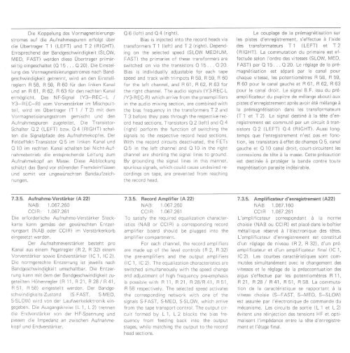
Die Koppelung des Vormagnetisierungsstromes<br />
auf die Aufnahmespuren erfolgt über<br />
die Übertrager T 1 (LEFT) und T2 (RIGHT).<br />
Entsprechend der Bandgeschwindigkeit (SLOW,<br />
IVED, FAST) werden diese Übertrager primärseitig<br />
eingeschaltet (O 15.. . O20). Die Einstellung<br />
des Vormagnetisierungsstromes nach Bandgeschwindigkeit<br />
getrennt, wird an den Einstellreglern<br />
R 58, R 59, R 60 für den linken Kanal<br />
und an R 61, R 62, R 63 für den rechten Kanal<br />
ermöglicht. Das NF-Signal (Y3-BEC-L /<br />
Y3-REC-R) vom Vorverstärker im Mischpultteil,<br />
wird im Übertrager \T 1 I 12) mit dem<br />
Vormagnetisierungsstrom gemischt und den<br />
Aufnahmespuren zugeleitet. Die Transistor-<br />
Schalter O2 (LEFT) bzw. O4 (RIGHT) schalten<br />
die Sionalpfade des Aufnahmekopfes. Der<br />
Feldeffekt-Transistor O 5 im linken Kanal und<br />
Q 10 im rechten Kanal schalten bei Nicht-Auf'<br />
nahmebetrieb die entsprechende Leitung zum<br />
Aufnahmekopf an Masse. Diese Abblockung<br />
schützt das Band vor störenden Fremdeinflüssen<br />
und somit vor ungewünschten Bandaufzeichnungen.<br />
O 6 (left) and O 4 (riqht).<br />
Bias is injected into the record heads vla<br />
transformers T 1 (left) andf 2 (right). Depending<br />
on the selected speed (SLOW l\4EDlUlV,<br />
FAST) the primaries of these transformers are<br />
switched on via the transistors O 15 . . . O 20.<br />
Bias is individually adjustable for each tape<br />
speed and track with trimpots R 58, R 59, R 60<br />
for the left channel, and R 61, F 62, R 63 for<br />
the right channel. The audio signals (Y3-REC-L<br />
/Y3-REC-R) which arrive from the preamplifiers<br />
in the audio mixing section, are combined with<br />
the bias frequency in the transformers T 2 and<br />
T 3 before they pass through the respective record<br />
head sections. Transistors O 2 (left) and O 4<br />
(right) perform the function of switching the<br />
signals to the respective record head sections.<br />
With the record circuits deactivated, the FETs<br />
O5 in the left channel and O 10 in the right<br />
channel are shorting the signal lines to ground.<br />
By grounding the signal lines in this manner,<br />
spurious signals, which could cause undesired recordings<br />
on tape, are prevented from reaching<br />
the record head.<br />
Le couplage de la prdmagndtisation sur<br />
les pistes d'enregistrement, s'effectue ä l'aide<br />
des transformateurs T 1 (LFFT) et f 2<br />
(RIGHT). La commutation du primaire est effectude<br />
selon l'ordre des vitesses (SLOW, MED,<br />
FAST) par O '1 5 . . . O 20. Le rdglage de la pr6-<br />
magn6tisation est sÖpard par le canal pour<br />
chaque vitesse, les potentiomÖtres R 58, R 59,<br />
R 60 pour le canal gauche et R 61, R 62, R 63<br />
pour Ie canal droit. Le signal B.F. issu du pr6-<br />
amplif icateur du pupitre de m6lange abouti aux<br />
pistes d'enregistrement aprös avoir 6t6 mölange ä<br />
la p16magn6tisation dans les transformateurs<br />
(T 1 et T2). Le signal destin6 ä la tÖte d'enregistrement<br />
est commut6 par un circuit ä transistors<br />
O 2 (LEFT) O4 (RIGHT). Aussi longtemps<br />
que l'enregistrement n'est pas en fonction,<br />
les transistors ä effet de champs O 5, canal<br />
gauche et Q 10 canal droit, court-circuitent les<br />
connexions de t6te ä la masse. Cette pröcaution<br />
est destinde ä protdger la bande contre toute<br />
magndtisation parasite inddsirable.<br />
7.3.5. Aufnahme-Verstärker (A 22)<br />
NAB: 1.061 .260<br />
CCI R: 1 .061 .261<br />
Die erforderliche Aufnahme-Verstärker Steckkarte<br />
kann gemäss der gewünschten Entzerrungsart<br />
(NAB oder CCIR) im Verstärkerkorb<br />
eingesetzt werden.<br />
Der Aufnahmeverstärker besteht pro<br />
Kanal aus einem Pegelregler \R2, R 32) einem<br />
Vorverstärker sowie Endverstärker (lC 1, lC2).<br />
Die normgerechte Entzerrung ist jeweils nach<br />
Bandgeschwindigkeit umschaltbar. Die Entzerrung<br />
kann mit dem der Bandgeschwindigkeit zugeteilten<br />
Höhenregler (R 11, R 21,R28 I R41,<br />
R51, RbB) eingästellt werden. Der Bandgeschwindigkeits'Zustand<br />
(S-FAST, S-l\4ED,<br />
S-SLOW) wird von der Laufwerkelektronik eingegeben.<br />
Die Ausgangskreise (L 1, L 2) trennen<br />
die Endverstärker von der HF-Spannung und<br />
passen die lmpedanz an zwischen Aufnahmekopf<br />
und, Endverstärker.<br />
7.3.5. Record Amplifier (A 22)<br />
NAB: 1.061 .260<br />
CCI R: 1.061 .261<br />
To satisfy the required equalization characteristics<br />
(NAB or CCIR) a corresponding record<br />
amplifier board should be plugged lnto the<br />
amplif ier compartment.<br />
For each channel, the record amplifiers<br />
are made up of the level controls (R 2, R 32)<br />
the pre-amplifiers and the output amplifiers<br />
(lC 1, lC 2). The equalization characteristics are<br />
switched simultaneously with the speed change<br />
and adjustment of high frequency pre-emphasis<br />
is possible with R 11, R21 , R2BlR41 , R51 ,<br />
R 58 respectively. The selected speed activates<br />
the corresponding network with one of the<br />
signals S-FAST, S-lVED, S-SLOW, which arrive<br />
from the tape transport control. The output circuit<br />
formed by L 1, L2 blocks the bias frequency<br />
from feeding back into the output<br />
stages, while matching the output to the record<br />
head sections.<br />
7.3.5. Amplificateur d'enregistrement (A22)<br />
NAB 1.067.160<br />
ccrR 1.o6t .261<br />
L'amplificateur correspondant ä la norme<br />
choisie (NAB ou CCIR) est plac6 dans le boitier<br />
m6tallique rdserv6 ä l'6lectronique des tetes.<br />
L'amplificateur d'enregistrement est constitud<br />
d'un r6glage de niveau (82, R32), d'un pr6-<br />
amplificateur et d'un amplificateur final (lC '1 ,<br />
lC2). Les courbes caractdristiques sont commutdes<br />
simultan6ment avec le changement des<br />
vitesses et Ie rdglage de la prdaccentuation des<br />
aigus s'effectue par les potentiomötres R '1 1,<br />
R21, R2B I R 41, R 51, B 58. La commutation<br />
de la caractdristique se rapportant ä la<br />
vitesse choisie (S-FAST, S-MED, S-SLOW)<br />
est assur6e par l'6lectronique de commande du<br />
m6canisme. Les circuits de sortie (L 1 et L 2)<br />
6vitent une rdinjection des tensions HF et optimalisent<br />
l'imp6dance entre Ia töte d'enregistrement<br />
et l'6tage f inal.


