Untitled - Revoxsammler
Untitled - Revoxsammler
Untitled - Revoxsammler
Create successful ePaper yourself
Turn your PDF publications into a flip-book with our unique Google optimized e-Paper software.
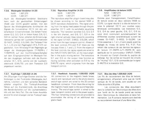
7.3.6. Wiedergabe-Verstärker (A 23)<br />
NAB: 1.067.210<br />
CCI R: 1.061 .271<br />
Auch die Wiedergabe-Verstärker Steckkarte<br />
kann nach der gewünschten Entzerrungsart<br />
(NAB oder CCIR) gewählt werden. Von den<br />
Spuren des Wiedergabekopfes durchlaufen die<br />
Signale die Vorverstärker (lC 1) mit den umschaltbaren<br />
Entzerrerkreisen. Die Schalt-Transistoren<br />
O 2, O 3, O 4 im linken Kanal; O 6, O 7,<br />
Q B im rechten Kanal, schalten die Entzerrungsnetzwerke<br />
gemäss den Laufwerk-lnformationen<br />
(S-FAST, S-MED, S-SLOW). Die Tiefpass-Filter<br />
(L 1, L 2) sind den Pegelreglern (R 5, R 27) vorgeschaltet.<br />
Vom Mittelabgriff der Pegelregler gelangen<br />
die Wiedergabe-Signale (Y-REPR-L /<br />
Y-REPR-R) auf den Vor/Hinterband-Schalter<br />
auf dem Eingangsverstärker im Mischpult-Teil.<br />
An den Ausgängen befinden sich die Stummschalter<br />
(O 1, O 5), welche von der Laufwerkelektronik<br />
(S-IVUTE) und dem Transistor O I<br />
angesteuert werden.<br />
7.3.6. Reproduce Amplifier (A 23)<br />
NAB: 1.067.27O<br />
CCI R: 1.067.271<br />
The reproduce amplifier plug-in board may also<br />
be chosen according to the desired NAB or<br />
CCIR reproduce characteristic. The signal arriving<br />
from the replay head passes through the preamplifier<br />
(lC 1) with its switchable equalizing<br />
networks. The transistor switches O 2, O 3, O 4<br />
in the left channel, and O 6, O 7, O B in the<br />
right channel activate these networks according<br />
to the signal S-FAST, S-MED, S-SLOW, which<br />
arrive from the tape transport control. Ahead of<br />
the level controls R 5 and R 27 there are the<br />
low-pass filters L 'l and L 2. From the wipers of<br />
the level controls the replay signals are wired to<br />
the INPUT/TAPE SWITCH, on the input amplifier<br />
in the audio mixing section. The transistors<br />
O 1 and O 5 on the output lines function as<br />
muting switches when activated via O 9 by the<br />
S-MUTE signal, which originates from the tape<br />
transport control.<br />
7.3.6. Amplificateur de lecture (A23)<br />
NAB 1.067.270<br />
cctR 1.067.271<br />
Comme pour l'enregistrement, l'amplificateur<br />
de lecture existe en deux versions (NAB ou<br />
CCI R). Le signal rdcoltd ä la t6te de lecture traverse<br />
le pr6ampli (lC1) aux courbes caract6ristiques<br />
commutables. Les transistors O 2,<br />
O 3, O 4 du canal gauche, O 6, O 7, O B du<br />
canal droit commutent automatiquement les<br />
diffdrentes courbes caract6ristiques suivant les<br />
vitesses (S-FAST, S-MED, S-SLOW). Les<br />
filtres passe-bas L 1 et L 2 sont plac6s avant les<br />
r6glages du niveau de sortie R 5, R 27. Puis<br />
venant des curseurs de ces derniers les signaux<br />
de lecture (Y-REPR-L/Y-REPR-R) sont<br />
appliquds sur le commutateur (INPUT-TAPE)<br />
se trouvant sur l'ampli d'entr6e du pupitre de<br />
mdlange. Sur les sorties se trouvent les circuits<br />
de "muting" (O 1, O 5) commandös par le signal<br />
S-MUTE et le transistor O 9.<br />
7.3.7. Kopfträger 1.O2O.822 (A241<br />
Am 20-poligen Kopfträger-Stecker sind die Verbindungen<br />
zu den Tonköpfen (Wiedergabe, Aufnahme,<br />
Löschen) und dem optischen Bandendschalter<br />
eingelötet. Die Tonkopf-Anschlüsse<br />
führen auf die Kopfelektronik, die Anschlüsse<br />
des Bandendschalters auf die Laufwerkelektronik<br />
und den Netz-Teil. Die vier f reien Anschlüsse<br />
sind für einen etwaigen vierten Tonkopf reserviert.<br />
7.3.7. Headblock Assembly 1.O2O.822 lA24l<br />
All connections to the magnetic heads (erase,<br />
record and reproduce) and to the photo-electric<br />
end-of-tape switch are wired to the 20 contact<br />
headblock connector. From there the wiring for<br />
the magnetic heads leads to the sound head electronics.<br />
The end-of-tape switch is wired to the<br />
tape transport control and to the power supply.<br />
The four remaining connections are provided to<br />
accomodate the wiring of an additional magnetic<br />
head.<br />
7.3.7. Bloc des tetes 1.020.822 lA.24l<br />
Les fils de raccordement des t6tes de lecture,<br />
enregistrement, effacement ainsi que de l'arr6t<br />
optique de fin de bande, sont soudds sur une<br />
fiche de sortie ä 20 pöles.<br />
Les connexions des tetes aboutissent<br />
dans la corbeille de l'ölectronique des tetes alors<br />
que l'arret de fin de bande prend ses racines<br />
dans l'ölectronique du m6canisme et dans l'alimentation.<br />
Les 4 contacts restants sont destinds<br />
au raccordement 6ventuel d'une 4öme töte.


