

H51308-v0A Manuale Istruzioni VTNC - Rhoss
H51308-v0A Manuale Istruzioni VTNC - Rhoss
H51308-v0A Manuale Istruzioni VTNC - Rhoss

Create successful ePaper yourself
Turn your PDF publications into a flip-book with our unique Google optimized e-Paper software.
SECTION II: INSTALLATION AND MAINTENANCE<br />
II.2.3<br />
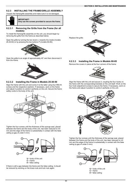
INSTALLING THE FRAME/GRILLE ASSEMBLY<br />
Unpack the frame/grille assembly and make sure it is not damaged.<br />
IMPORTANT!<br />
Only use the screws provided to secure the frame.<br />
II.2.3.1 Removing the Grille from the Frame (for all<br />
models)<br />
To install the frame/grille assembly on the unit, you should begin by<br />
removing the grille from the frame as described below.<br />
Open the grille by turning the two levers L towards the inside (models<br />
25-30-50) or by pressing the two buttons P (models 60-85):<br />
Replace the grille:<br />
45°<br />
L<br />
Open the grille to an angle of approximately 45° and then disconnect it<br />
from the frame:<br />
II.2.3.3 Installing the Frame in Models 60-85<br />
Remove the covers in place at the four corners of the frame:<br />
45°<br />
II.2.3.2 Installing the Frame in Models 25-30-50<br />
Align the frame with the unit and screw it to the latter using four M5x16<br />
screws and the respective washers. If necessary, work on the frame<br />
and adjust it position to centre it perfectly on the unit. Secure the frame<br />
safety cords to the body of the unit:<br />
Align the frame with the unit and secure it, coupling the four hooks on<br />
the frame with the corresponding brackets on the unit itself. Work on the<br />
four hook adjustment screws to secure the frame. If necessary, work on<br />
the frame and adjust it position to centre it perfectly on the unit.<br />
Tighten the four screws until the thickness of the sponge seal, placed<br />
between the frame and the body of the unit, has been reduced to 4-6<br />
mm and the edge of the frame is substantially in contact with the false<br />
ceiling (a gap of under 5 mm):<br />
8<br />
U<br />
4-6 mm<br />
Tighten the four screws until the thickness of the sponge seal, placed<br />
between the frame and the body of the unit, has been reduced to 4-6<br />
mm and the edge of the frame is substantially in contact with the false<br />
ceiling (a gap of under 5 mm):<br />
C<br />
8<br />
U<br />
4-6 mm<br />
U = body of the unit<br />
C = frame<br />
8 = false ceiling<br />
If there is still a gap between the frame and the false ceiling, it should<br />
be reduced by working on the brace nuts and lock nuts again:<br />
C<br />
U = body of the unit<br />
C = frame<br />
8 = false ceiling<br />
40


