

H51308-v0A Manuale Istruzioni VTNC - Rhoss
H51308-v0A Manuale Istruzioni VTNC - Rhoss
H51308-v0A Manuale Istruzioni VTNC - Rhoss

You also want an ePaper? Increase the reach of your titles
YUMPU automatically turns print PDFs into web optimized ePapers that Google loves.
SECTION II: INSTALLATION AND MAINTENANCE<br />
1<br />
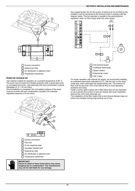
Any supplementary fan for the suction of external air (to be fitted by the<br />
installer) must be connected to the terminal board in keeping with the<br />
diagram below. The fan operates in parallel to the electrothermal<br />
regulation valve, so that it stops when the valve closes.<br />
230V<br />
5<br />
6<br />
7<br />
L N 1 2<br />
5<br />
170<br />
155<br />
4<br />
T<<br />
2<br />
337<br />
364<br />
3<br />
External renewal air<br />
1 Access connection<br />
5 External air inlet<br />
6 Air distribution in adjacent room<br />
7 Polystyrene membrane<br />
Use material suitable for operation at a constant temperature of 60 °C.<br />
The ducts may be made from flexible polyester (with a spiral steel core)<br />
or corrugated aluminium, clad externally with anti-condensation material<br />
(fibreglass of 12 ÷ 25 mm thick).<br />
Once installation is completed, the uninsulated surfaces of the ducts<br />
must be covered with anti-condensation insulation (for example,<br />
expanded neoprene of 6 mm thick).<br />
1 Unit terminal board<br />
2 Antifreeze thermostat<br />
3 Speed variator<br />
4 External fan motor<br />
5 230 V relay<br />
For winter operation with external air supply, we recommend installing<br />
an antifreeze thermostat calibrated at 2°C, with the bulb on the water<br />
outlet pipe, which intercepts the supplementary fan. The external air<br />
flow must be less than 10% of the total air flow to avoid operating<br />
problems and noise.<br />
Install a suction grille outside with a filter frame that can be inspected,<br />
so as to prevent the suction of dust and leaves that could irreparably<br />
obstruct the unit's heat exchange coil.<br />
The installation of the filter means that a duct closure damper does not<br />
need to be installed during longs periods out of use.<br />
6<br />
5<br />
1<br />
Ø<br />
B<br />
6<br />
7<br />
3<br />
4<br />
2<br />
60-85<br />
B Ø mm 75<br />
1 Access connection<br />
2 Pipe clip<br />
3 6 mm neoprene seal<br />
4 Insulated, flexible duct<br />
5 External air inlet<br />
6 Air distribution in adjacent room<br />
7 Polystyrene membrane<br />
IMPORTANT!<br />
Failure to observe these instructions may cause<br />
dripping due to condensation. The manufacturer<br />
may not be held liable for any damage.<br />
42


