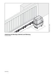
ProMatic - Hormann.fr
ProMatic - Hormann.fr
ProMatic - Hormann.fr
- No tags were found...

You also want an ePaper? Increase the reach of your titles
YUMPU automatically turns print PDFs into web optimized ePapers that Google loves.
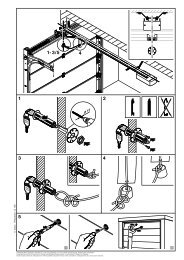
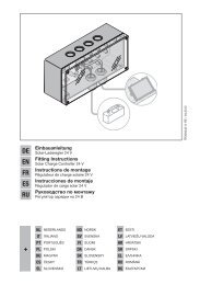
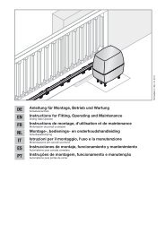
ENGLISH2 Installation Instructions2.1 Required clearance for installing the operatorWhen installing the operator, the clearance between thedoor at its highest point of travel and the ceiling mustbe at least 30 mm (see figures 1.1a / 1.1b).2.2 The mechanical door latches on an up-and-over doormust be immobilised (see figure 1a). In the case of doormodels not listed here, the catches must be locked onsite.2.3 On a sectional door the internal mechanical latch mustbe completely dismantled (see figure 1b).ATTENTIONWhen installing the operator, the pullcord on the door must be removed(see figure 1.2b).2.4 NoteUp-and-over doors with a forged iron door handleContrary to the illustrated section (see figure 2a / 3.2a),these doors require the lintel bracket fastening and thedoor link bracket to be fitted off-centre.2.5 Central locking on a sectional doorFor sectional doors with a centrally positioned lock, fitthe lintel bracket fastening and the door link bracket offcentre(see figure 2b).2.6 Off-centred reinforcement profile on a sectional doorIn the case of an off-centred reinforcement profile on asectional door, fit the door link bracket to the nearestreinforcement profile on the left or right (see figure 2b).NoteContrary to the illustrated section, for timber doorsuse the wood screws 5 x 35 <strong>fr</strong>om the pack of screwssupplied with the door (3 mm Ø drill hole).2.7 Tensioning the drive beltThe operator boom’s toothed belt is already set at thefactory for optimum tension. During the starting andbraking phases of large doors it can happen that thebelt hangs out of the boom profile temporarily.This, however, is of no technical disadvantage nor doesit have any negative effect on the operator's function andservice life.CAUTIONDo not insert fingers into the boom whilethe door is moving ➜ risk of crushedfingers!3 Putting into Service / Connecting AdditionalComponents / Operation3.1 Establishing the door's end-of-travel positionsby installing the limit stops1) Insert the limit stop for the OPEN end-of-travel looselyinto the boom between the carriage and the drive unit(see figure 4) and after fitting the door link (see figure6.1a / 6.2a / 6.1b / 6.2b) push the door by hand intothe OPEN end-of-travel position ➜ the limit stop ispushed into the correct position (see figure 7).2) Fix the limit stop for the OPEN end-of-travel position.3) Insert the limit stop for the CLOSE end-of-travel looselyinto the boom between the carriage and the drive unit(see figure 4) and push the door by hand into the CLOSEend-of-travel position ➜ the limit stop is pushed closeto the correct position (see figure 8).4) Push the limit stop for the CLOSE end-of-travel positionapprox. 1 cm further in the CLOSE direction and thenfix in place.NoteIf you are unable to push the door manually into the desiredOPEN or CLOSE end-of-travel positions, this indicates thatthe door mechanics are too sluggish to be used with thegarage door operator and must therefore be checked (seesection 1.1.2)!3.2 Notes on work involving electricsATTENTIONThe following points apply to all workinvolving electrics:- Electrical connections may only be made by aqualified electrician!- Onsite electrical installation must comply withthe relevant safety regulations (230/240 V AC,50/60 Hz)!- Before working on the operator, always unplug<strong>fr</strong>om the mains!- External voltage at any of the controls connectingterminals will completely destroy the electronics(exception terminal .6, .5, .8)!- To avoid malfunctions, ensure that the controlcables of the operator (24 V DC) are laid in aninstallation system separate to other supply lines(230 V AC)!3.3 Putting the operator into serviceThe operator features a memory (fail-safe even in theevent of a power failure) where the data specific to thedoor (distance of travel, necessary forces for door movementetc.) laid down during learn cycle (programming)are stored and which are updated during subsequenttravel cycles. This data is only applicable to this particulardoor. If any other door is to be used or if the running actionof the door has greatly changed (e.g. after subsequentlyadjusting limit stops or fitting new springs etc.),the data must be deleted and the operator then reprogrammed.3.3.1 Deleting the door data (see figure 18)In the ex factory state, the door data is deleted and theoperator can be immediately programmed ➜ see section3.3.2 - Programming the operator.If re- programming is desired or becomes necessary,the door data can be deleted as follows:3806.2004 TR10A014 RE